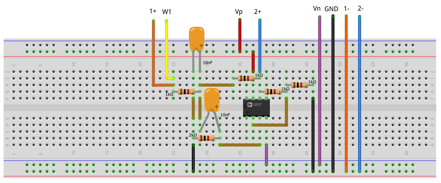
Narrow Band Pass Filter Circuit Diagrams are a crucial component of many electronic systems and devices, used to ensure the desired signal remains filtered and isolated from external interference. This type of filter design utilizes a frequency response that is tailored towards specific frequency stop bands, allowing for much greater control over the signal than classic low-pass or high-pass filters.
The circuit diagrams associated with this type of filter design can range from relatively simple to quite intricate, depending on the required specifications of the application. In most cases, the key components include operational amplifiers, resistors, capacitors, and inductors. The design process begins by determining what frequencies need to be passed and what ones need to be blocked, and then configuring the various components to achieve this result. As with other electronics designs, there are often areas of trade-off that have to be considered, such as filtering quality versus complexity and cost-effectiveness.
For many, these circuit diagrams may seem daunting at first, but with some practice and understanding, it is possible to not only understand the basics of this type of filter design but also be able to create a working prototype. Having a grasp of the underlying principles of electrical engineering is essential for designing a successful narrow band pass filter, as this can then help identify areas that require further modification. In addition, once the design is finalized, it is important to test the design using a simulator or actual testing apparatus to ensure the desired results are attained.
Active Narrow Band Pass Filter Design Electronics Forums

Band Pass Filter Circuit Diagram Types Frequency Response

Narrow Band Audio Bandpass Filter

Electronic Projects

Band Pass Filter Linear Integrated Circuit Questions And Answers Sanfoundry

Band Pass Filter Circuit Diagram Types Frequency Response

Active Band Pass Filter Characteristics 5 Important Use

Band Pass Filters Electronics Textbook

Chapter 3 Acti Ve Filte Active Filter Q
Chapter 15 Active Filters

Band Pass Filter Circuit Diagram Types Frequency Response

Band Pass Filter Circuit Diagram Types Calculator And Its Applications

Steps For Lumped Element Bandpass Filter Circuit Design A 3 Pole Scientific Diagram
Active Narrow Bandpass Filter Multisim Live

Types Of Active Band Pass Filters The Engineering Knowledge

What Is Band Pass Filter How To Design It Sm Tech

What Is A Bandpass Filter Definiton Design Response Curve And Applications Of Electronics Coach

Design Configuration For Narrow Band Bandpass Filter With Fabricated Scientific Diagram

Activity Active Filtering Analog Devices Wiki