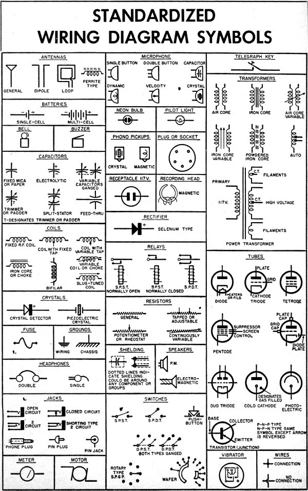
Wiring diagrams are the standard for any electrical work in both residential and commercial buildings. They provide an essential toolset for understanding the building’s wiring system, as they provide a visual reference for what is happening, where it is happening, and how it is connected. Wiring diagrams not only help electrical and maintenance personnel understand the electrical interconnections of the building, but also help diagnose and troubleshoot possible problems with the building’s electrical installation.
The most common format for wiring diagrams is the ladder diagram, which shows in clear detail every switch, every conductor, and all the points at which the conductors come together or diverge. This allows tracing of the circuit and finding of faults. The symbols used to represent components of a circuit vary from country to country, but the basic ideas remain the same. Ladder diagrams may be supplemented with additional diagrams, such as a wiring schematic, a panelboard diagram, and other graphical representations to make the diagram easier to understand.
Modern wiring systems in commercial buildings are often complex and require sophisticated wiring diagrams to trace the circuitry. In addition, smart wiring and automation systems are increasingly being integrated into the electrical system design, making the diagrams more complex. To accommodate these newer technologies, various software packages have been developed that allow users to create wiring diagrams quickly and easily. These programs can even generate parts lists, allowing for an efficient automated ordering process.
In summary, wiring diagrams are an essential tool when installing, troubleshooting, and maintaining electrical systems in both residential and commercial buildings. While the basic format remains the same, modern technology has made wiring diagrams more complex and easier to understand. With the help of dedicated software, generating wiring diagrams is now simpler than ever before.

Household Electric Circuits

Wiring Guides

Wiring Diagrams

Tator Diagrams Standard Shawntec

Lindy Fralin Wiring Diagrams Beautiful Guitar Bass
Wiring Diagram Acc Wire Color Codes Standard Features Tidewaterowners Com
Wiring Diagrams Rj45 Ethernet Cable Utp Diagram There Are Two Standards That For Connector They Eia Tia 568a And 568b Can Also Be Known

Wiring Diagrams Blackwood Guitarworks

How To Construct Wiring Diagrams Controls

Regular Tv Diagram

Given A Standard Bus Connection With Two Control Chegg Com

Wiring Diagram Information Manualzz

Intro To Electrical Diagrams Technology Transfer Services

Standard Strat Wiring Diagram

Wiring Diagrams Explained How To Read Upmation

Aim Manual Page 55 Single Phase Motors And Controls Motor Maintenance North America Water Franklin Electric

Wiring Diagrams

Wiring Diagrams Explained How To Read Upmation

Standardized Wiring Diagram Schematic Symbols April 1955 Por Electronics Rf Cafe

Wall Outlet Wiring Diagram
