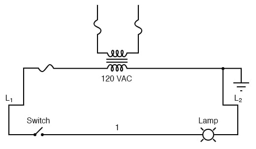
Electric diagrams are complex images used to depict electrical and electronic systems. They are usually created with special software or hand-drawn using a pencil and eraser. These diagrams can be used for a variety of purposes, including troubleshooting electrical problems, analyzing the performance of circuits, or teaching electrical theory.
Electric diagrams can be divided into two main categories: schematic diagrams and wiring diagrams. Schematic diagrams are focused on depicting the overall functional relationships between components in an electrical circuit. Wiring diagrams, by contrast, are more concerned with depicting the physical layout of the components in the circuit. Both types of diagrams are helpful in troubleshooting electrical faults and improving circuit performance, but they serve different purposes.
Given the complexity of electrical circuits, it’s important to pay attention to detail when drawing electric diagrams. Components should be labeled clearly and accurately, and the diagrams should be organized in a way that makes sense. This will make analyzing and understanding them much easier. Additionally, it’s also important to use consistent symbols and conventions throughout the diagram so that anyone looking at it can understand what it’s trying to represent without having to guess. Knowing the different types of electric diagrams and how to create them are key skills for any electrician or electronics technician.

Electric Circuit Diagrams Lesson For Kids Transcript Study Com

Guide To Wiring Diagrams The Family Handyman

How To Construct Wiring Diagrams Controls

The Wiring Diagram And Physical Layout Of Equipment Inside Motor Control Centre Eep

Single Line Electrical Diagrams Electric Power Measurement And Control Systems Automation Textbook
Engineering Symbology Prints And Drawings Module 3 Electrical Diagrams Schematics

Ladder Diagrams Logic Electronics Textbook

Electrical Schematic Diagram Elementary Wiring A2z

Sample Circuit Diagrams From Both The Static Labels S Conditions Scientific Diagram

How To Draw Electrical Diagrams And Wiring
Types Of Electrical Wiring Technology Facebook

Electrical Design Verification Siemens Software

Circuit Diagram Of The Generator Connected With Three Phase Resistive Scientific

Schematic Symbols The Essential You Should Know

Types Of Electronic Diagrams

What Is The Meaning Of Schematic Diagram Sierra Circuits

Single Line Diagram How To Represent The Electrical Installation Of A House Stacbond

Electrical Schematic Diagram Elementary Wiring A2z
