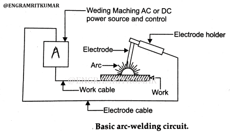
Welding is a complex, high-stakes operation with components that can be baffling even to experienced technicians. It’s essential that welders fully understand the particulars of their projects, including welding circuit diagrams. Circuit diagrams are essentially an electrical blueprint that detail the connections between components, from switching power sources to grounding systems. They provide a visual snapshot of the entire welding system and allow quick, easy troubleshooting.
The complexity of a welding circuit diagram can range from simple off-the-shelf systems to advanced custom-made designs. In most cases, welding circuit diagrams include a number of different components connected together, such as: a power source, a ground system, switching units, control systems, temperature monitors, and more. Understanding how these components fit together is essential for successful welding operations. One key element of a welding circuit diagram is the transformer, which converts electrical energy from the power source into welding current. This current is used to create the sustained heat necessary for welding. Additionally, the circuit diagram should contain safety information about the welding system, including wire size, amperage and voltage ratings, and grounding requirements.
To successfully interpret a welding circuit diagram, it’s important to know the symbols and conventions associated with this type of diagram. Commonly used symbols, abbreviations, and terms should be easily recognizable. Additionally, it helps to have a thorough understanding of basic electrical circuitry and how components work together. While welding circuit diagrams may appear complicated at first, they ultimately provide valuable information regarding the entire welding system, allowing welders to better assess and manage their projects.

After The Restructuring Of Ac And Dc Arc Welding Machine Circuit Under Other Circuits 59032 Next Gr

Welding Machine Schematics Service Manual Electronics Projects Circuits

Us8410399b2 Capacitor Charge And Discharge Circuit For Fastener Welding Google Patents

A Power Processing Diagram Of The Selma Arc 160 Welding Inverter Scientific

Arc Welding Transformer Power Regulation Schematic

Simplified Diagram Of Primary Inverter Welding Machine Circuits Scientific

Wiring Diagram Arc Welding Power Inverters Circuit Schematic Scientific Angle Text Electrical Wires Cable Png Pngwing

25khz Using Thyristor Inverter Welding Machine Circuit Under Demodulators Circuits 58725 Next Gr
Electric Diagram Of D C Flash Welding Machine Scientific

Us9199327b2 Portable Igbt Arc Welding Machine Google Patents

De202009008641u1 Igbt Inverter Arc Welding Machine Google Patents

Welding Electrical Circuit

Ar 300 Dc Arc Welding Machine Circuit Under Other Circuits 58975 Next Gr

100a Tig Welding Circuit Igbt Uc3845 Irg4pc50u Etd59 Electronics Projects Circuits

Structures Of Welding Systems A Single Phase Ac System B 3 Dc Scientific Diagram

Arc Welding Definition Equipment Working Diagram Advantages Pdf Learn Mechanical

Anyone Got Mig Pcb Schematics Welding Forum

Simple Controller For Alternator Based Welders

Smps Welding Inverter Circuit Homemade Projects