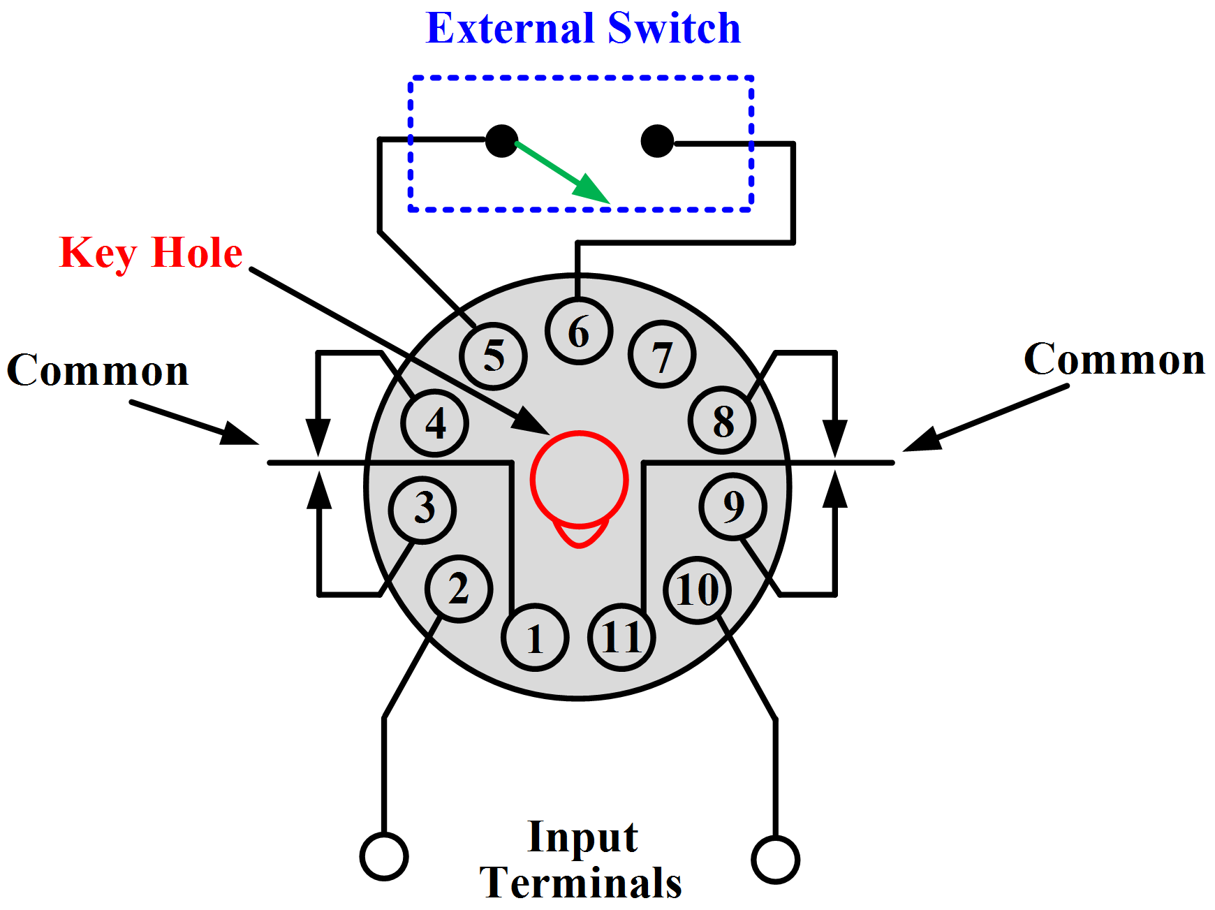
Timer Relay Connection Diagrams are vital for anyone working with electrical wiring and devices. They provide a simple way of connecting components to one another, enabling electricians to easily identify and troubleshoot any circuitry issues. Understanding how these diagrams are used is an essential part of any electrical technician's knowledge base.
Timer Relay Connection Diagrams use a combination of symbols and colors to illustrate the different types of terminals and connections that are required in order to complete the circuit. These diagrams can be used in conjunction with other tools, such as wire color coding charts, to ensure that all the proper connections and wires are being connected properly.
Timer Relay Connection Diagrams typically feature a detailed, step-by-step process that explains each component of the system, from the power source (usually a battery) to the ground connection and everything in between. This provides electricians with the insight they need to complete the job quickly and safely. Additionally, these diagrams often come with helpful annotations or tips that can help inexperienced technicians recognize and address any issues they may encounter during the installation process.

An Automatic Cw T R System For Vintage Stations Ac Wiring

Nte8 Time Delay Relay Chint

Time Relay Delay Manufacturer From China Alion
Electronic Time Relays
Time Delay Relays

Digital Timer Relay 8 Pin 24v Dc 110 240v Ac Ato Com

Solid State Timer Relay Electrical Academia

Time Delay Relay Circuit With 555

Ics Time Delay Module Applications And Wiring

Motor Control Systems Relays Part C

Automatic On Off Relay Circuit
Delay Timer Wiring Cr4 Discussion Thread

Time Delay Relay Basics Circuit And Applications

Circuit Diagram For The Delay Timer Scientific

Time Delay Relay Module Digital Lcd Display 6 30v Control Timer Switch Trigger Cycle For Smart

Ah3 N 3a On Delay Time Super Relay 220v Inductive Proximity Sensor Photoelectric Capacity Solid State Pcb Timer
326 327 Series Time Delay Relays On Struthers Dunn
Eee Tutors 8 Pin Timer Relay Wiring Connection Diagram Controlling Facebook By 3 Phase Motor Series Provide
