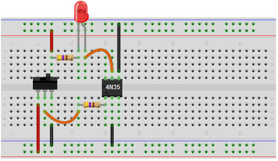
Optocoupler circuits are sophisticated electronic devices used to control the electrical current from one circuit to another. These circuits are typically used to isolate two separate circuits, such as two power sources, in order to protect sensitive components from spikes in voltage or current. Optocouplers are commonly used in various industrial applications, from telecommunications equipment to medical imaging systems, and can provide an effective means of transferring electrical signals between circuits while keeping them isolated from one another. The diagram of an optocoupler circuit is a vital tool used by engineers and technicians to design and troubleshoot these devices.
The optocoupler circuit diagram will typically show an input signal coming from one circuit and being sent into an optocoupler. When the input signal is triggered, either through a series of electrical pulses or some type of digital signal, the output of the optocoupler is also triggered, sending the signal from one circuit to the other. This is done through an optical isolator, which is a device consisting of an LED and phototransistor, that uses light waves to transfer the electrical pulses.
The optocoupler circuit diagrams will typically show components such as resistors, capacitors, IC chips, and diodes, along with their respective values. Additionally, the diagrams will often show how the optocoupler is connected to other parts of the circuit, such as the power source or the input device. When correctly constructed, these sophisticated circuits can provide a reliable and efficient means of controlling electrical signals without any interference, making optocouplers an invaluable tool in many different industrial applications.

4n28 Optocoupler Pinout Datasheet Equivalents Features

What Is An Optocoupler And How It Works

Optoisolator Or Optocoupler Construction And Operating Principle Of Electrical4u

How An Optocoupler Works Eagle Blog

What Is Optocoupler Its Types And Various Application In Dc Ac Circuits

Pc817 Optocoupler Tester Circuit

Led Optocoupler Circuit

Solid State Relay Circuit Diagram Using Triac

Project How To Make A Relay Module With Optocoupler Latest Circuit Diagram Dip Electronics Lab

How To Build An Optocoupler Circuit

Optocoupler Circuit Diagram Circuitspedia Com

Lt4430 Datasheet And Product Info Analog Devices

Pc817 Optocoupler Pinout Working Applications Example With Arduino

4n28 Optocoupler Pin Configuration Specifications Its Applications

4 Optocouplers Schematic Module Resources Easyeda

What Is Optocoupler And How It Works

What Is An Optocoupler And How It Works

Optocoupler Schematic Diagram General Electronics Arduino Forum