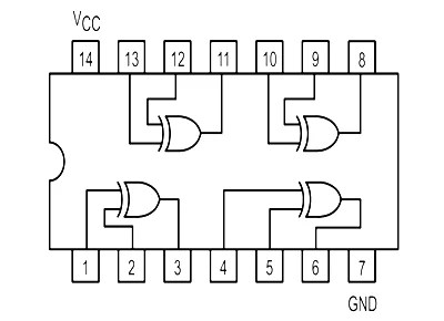
Nor Gate Pin Diagram is a type of logic gate, used to control electrical signals in a digital circuit. It is one of the fundamental building blocks of digital electronics and is used to create functions from basic logic gates. This gate takes two inputs and produces one output. When both inputs are high, the output is low. When either input is low, the output is high. The Nor Gate Pin Diagram is a simple but powerful tool for controlling electrical signals in a circuit.
Nor Gate Pin Diagrams are a great way to visualize the behavior of logic gates. This is a diagram that shows how a given gate operates with two different inputs. This can be used to show how a particular logic gate works in different situations. By looking at the Nor Gate Pin Diagram, it can be seen that when both inputs are high, the output is low. Conversely, when either input is low, the output is high. Understanding this behavior can be useful when constructing complex digital circuits.
The Nor Gate Pin Diagram is also a useful tool when troubleshooting circuits. By analyzing the diagram, it is possible to determine where there may be problems in the circuit. For example, if a circuit is not working as expected, looking at the Nor Gate Pin Diagram can help pinpoint the possible issues. With this diagram, it is possible to quickly identify potential errors or short circuits. This makes it an invaluable tool when it comes to understanding and troubleshooting digital circuits.

Xnor Gate Circuit Diagram Working Explanation
Draw The Logic Gate Diagram To Implement And Or Gates Using Nor Only Sarthaks Econnect Largest Online Education Community

Cd4001 An Ic With Four Nor Gates Build Electronic Circuits

Logic Nor Gate Electronics Lab Com

Electric Bugle Ic Diagrams
Logic Gate Symbols Or And Not Nor Nand Xor Xnor Etechnog

Explain The Logic Ex Nor Gate Exclusive And Its Operation With Truth Table Electronics Post

What Are Logic Gates Or And Not Gate With Truth Table Electronics Coach

Understanding Digital Buffer Gate And Logic Ic Circuits Part 3 Nuts Volts Magazine

Understanding Digital Buffer Gate And Logic Ic Circuits Part 4 Nuts Volts Magazine

Integrated Circuits Chips Electronics Nor Gate Pinout Functional Angle White Png Pngwing

04130 Jpg

Nor Gate Truth Table Circuit Diagram

Breadboard 2 Logic Multiple Gates Joe S Hobby Electronics

Nor Gate Truth Table Circuit Diagram

Solved 3 Repeat Part 2 B And C But With Nor Gates The Chegg Com

74ls02 Nor Gate Ic Pinout Features Equivalents Circuit Datasheet

Glossary Of Electronic And Engineering Terms Dual Input Nor Gate
