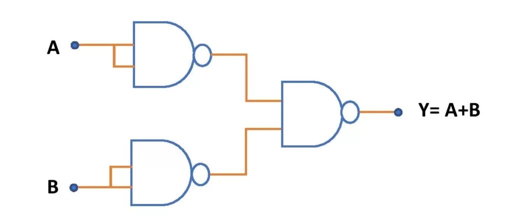
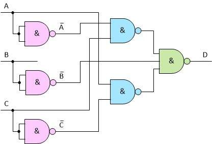
Nand Gate Schematic Diagram is a type of circuit that has become an essential part of the modern electronics industry. This diagram enables the electronic devices to function properly by controlling the flow of current.
A NAND gate schematic diagram consists of two transistors, connected in series along with resistors on both sides. This configuration allows the gate to control the flow of electrons from one transistor to the other. It can either block the flow or pass it through depending on the type of signal it receives. The transistors are held in a certain state, making them switch between ON and OFF states.
The importance of NAND gate schematic diagram lies in its ability to control the flow of current, thus allowing complex circuits and systems to be constructed. Without this type of circuit, many of the modern technological advances wouldn’t be possible. From home automation, to medical devices, to self-driving cars, these useful diagrams are at the heart of them all. With the help of NAND gate schematic diagram, electronics engineers can effectively build complex circuits faster than before.
In conclusion, NAND gate schematic diagrams are essential for the proper functioning of many electronic systems and devices. These diagrams allow for more efficient circuit construction, which helps make possible some of the most exciting innovations of our time. By understanding its inner workings, engineers have made — and continue to make — huge advancements in the electronics industry. It is clear that NAND gate schematic diagrams are extremely important for the continued development of our technology and for our everyday lives.

Draw The Schematic Symbols For And Or Not Nand Gate Physics Shaalaa Com

Not And Or Gate Using Nand Circuit Diagram Edumir Physics

Digital Circuits Physical Lab

Lab

Digital Logic Nand Gate Universal Its Symbols Schematic Designs Ic Details All About Engineering

Nand Gate What Is It Working Principle Circuit Diagram Electrical4u

Schematic Diagram Of Two Input Transition Nand Gate Tag This Scientific

Nand Gate Truth Table Circuit Design Applications And Advantages

Cmos Gate Circuitry Logic Gates Electronics Textbook
2 Input Nand Gate Wquan01ee103finalproj
Lab6 Designing Nand Nor And Xor Gates For Use To Design Full Adders

Nand Gate Circuit Diagram And Working Explanation

Implementing Logic Functions Using Only Nand Or Nor Gates Eeweb

Nand As Universal Gate In Proteus The Engineering Projects

Ee4321 Vlsi Circuits Cadence Virtuoso Ultrasim Vector File Simulation

Nand Inverter Circuit Diagram Simple Free Not Gate Transistor Transpa Png 1200x1200 On Nicepng

Logic Nand Gate Electronics Lab Com

How To Build A Night Light Circuit With Nand Gate Chip

04141 Jpg