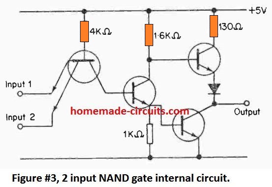
A Nand Gate Circuit Diagram Using Transistor is an essential component of any digital circuit design. The purpose of a NAND gate is to enable or disable the flow of electric current through connected wires and devices. It does this by accepting an input voltage and outputting an inverted version of the same signal. A simple transistor-based NAND gate circuit diagram can be implemented with just a few components.
The key component of a Nand Gate Circuit Diagram Using Transistor is the transistor itself. A transistor consists of three connections known as the emitter, collector, and base. The simplest transistor-based NAND gate circuit diagram uses two of these connections to provide the two inputs and one output. When using a single transistor to create this circuit, the emitter is connected to one of the two inputs and the collector is connected to the other input. The output is then connected to the base of the transistor.
When the two input signals are both at a high voltage, the output from the transistor is essentially a low voltage, allowing no current flow and thus disabling any connected wire or device. Conversely, when both of the input signals are at a low voltage, the transistor's output is a high voltage, which allows current to flow and thus enable any connected wire or device. This simple NAND gate circuit diagram using a transistor is the fundamental building block for all digital logic circuits.
These circuits can become more complex when additional transistors are added to provide additional outputs and connections or to switch multiple inputs. For instance, a multi-transistor NAND gate circuit diagram can be used to implement functions like the AND, NAND, OR, NOR, exclusive-OR, and exclusive-NOR logic functions. All of these functions can be performed by using just a handful of transistors, making them ideal for use in embedded systems and digital circuit designs.

Cs 250 Lab 1

Logic Gates Using Diodes And Transitor Circuit Fever

Nand Gate Truth Table Circuit Design Applications And Advantages

Nand Gate Digital Logic Gates Electronics Tutorial

Simple Circuits Using Ic 7400 Nand Gates Homemade Circuit Projects

Nor Gate Truth Table Symbol 3input Circuit Diagram Ic

Nand Gate Truth Table Circuit Design Applications And Advantages

Basic Logic Gates And Buffers

Digital Electronics Logic Gates Basics Tutorial Circuit Symbols Truth Tables

Csci 255 Building Logic Gates From Transistors

Npn Transistor Xor Gate Circuit Sully Station Technologies

Designing Not Gate Using Transistors

Simple Beeper Circuit Using Cd4011 2 Input Nand Gate Ic

From Transistors To Micro Processors 101 Computing

Resistor Transistor Logic Rtl

Nand Gate Truth Table Circuit Design Applications And Advantages

Nor Gate Using Diode And Transistor Dtl
Cmos Three State Gate Gated Output Driver Multisim Live

Diode Transistor Logic Dtl