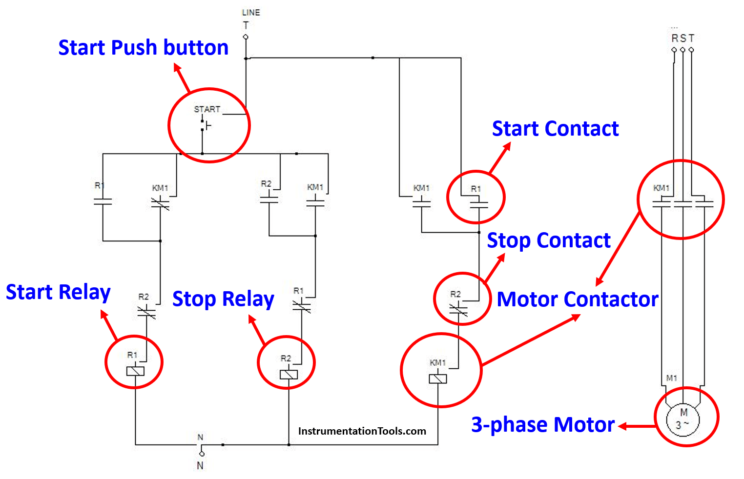
Motor Schematic Diagram Explanation is a detailed and precise explanation of the inner workings of electrical motors. The diagram shows all the essential components of an electric motor and their connections. It allows the user to understand how the motor works and identify any faults that may arise.
The schematic diagram is designed to show the different parts of the motor in a clear and concise way. It is typically structured in a linear fashion, beginning with the main elements (the rotor and stator) followed by the various subsystems (such as the wiring and controller). In this way, it is easy to follow the flow of information through the system. The diagram can also include additional details, such as the physical layout or even the electrical diagram, if necessary.
The schematic diagram can be used by technicians and engineers in a variety of ways. It can help to quickly identify faults in the system, troubleshoot problems or investigate why an electrical motor is not operating correctly. By using the schematic diagram, technicians and engineers can also verify the performance of existing systems and design new ones. This can be especially useful when designing complex systems, where the interaction of multiple parts requires careful consideration. With a detailed schematic diagram, each component's contribution can be easily visualized and understood.

Updated Brushless Controller Schematic 2015 Motors 3phase Inverters Schematics

Motor Classic Control Circuits Using Single Push On

How To Read Car Wiring Diagrams For Beginners Emanualonline Blog

Updated Brushless Controller Schematic 2015 Motors 3phase Inverters Schematics

Dc Motor Control Pwm With 555

Ac Servo Motor Working Principle Circuit Diagram Construction Characteristics Applications Electricalworkbook

Draw The Diagram Of Series Motor Bartleby

Star Delta Starters Explained The Engineering Mindset

Dc Series Motor Circuit Diagram Characteristics And Its Applications

Basics Of Universal Electric Motors

Dc Motor Sd Controller Electronic Schematic Diagram

Wiring Diagram A Comprehensive Guide Edrawmax Online

Unipolar Stepper Motor Driver Electronic Schematic Diagram

Types Of Single Phase Induction Motors Motor Wiring Diagram Electrical Academia

Schematic Diagram Of The Vehicle Powertrain Scientific

Solved 2 The Schematic Diagram Of An Elevator Driven By A Chegg Com

Ladder Diagram Schematic Wiring Electrical Academia

How Do Electric Motors Work Explain That Stuff