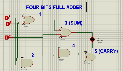
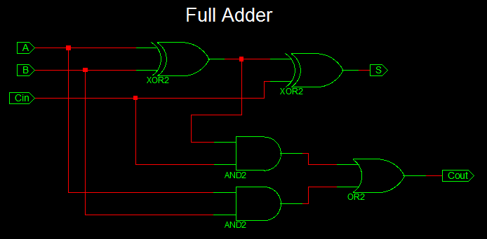
A full adder circuit is an essential component of any digital system, and understanding its purpose and structure is key to unlocking the potential of your project. A full adder circuit diagram using basic gates is a collection of logic gates that help to perform arithmetic functions on two numbers, such as adding, subtracting, multiplying, and dividing.
At its core, a full adder circuit is comprised of a few simple logic gates—AND, OR, and NOT—arranged in various combinations. These gates take two numbers as inputs and produce a result based on the logic gate used. For example, if you input two binary numbers into an AND gate, the output will be one when both the inputs are equal to one. Similarly, when two binary numbers are input into an OR gate, the output will be one when either one of the two inputs is equal to one.
Using these logic gates and their various combinations, a full adder circuit diagram can be created to perform various arithmetical operations on two numbers. This essentially means that with a bit of tinkering, you could use the circuit diagram to create a calculator! Moreover, if you know the right combination of logic gates for a specific operation, you could create your own custom logic systems with this powerful full adder circuit. From automating simple calculations to controlling complex circuitry, the possibilities are endless with this robust circuit design.

Full Adder Nand Equivalent Eeweb

Full Adder Circuit Theory Truth Table Construction

Half Adder And Full Circuit With Truth Tables

Full Adder

4 Bit Full Adder Using Logic Gates In Proteus The Engineering Projects

Vhdl Code For Full Adder

Advanced Tutorial Lesson 7 Building A Ripple Carry Adder Using Reusable Digital Devices Emagtech Wiki

Logic Gate Implementation Of Arithmetic Circuits De Part 11

Full Adder An Overview Sciencedirect Topics

Ripple Carry Adder 4 Bit Circuit Propagation Delay

Electronic Full Adder Circuit Based On Not And Or Logic Gates Scientific Diagram

Solved 5 Following Is A Nand Only 1 Bit Full Adder Circuit Chegg Com

Full Adder Circuit Diagram

Solved Q1 A Design Full Adder Circuit With Two Half Chegg Com
Solved Q1 Using The Full Adder Diagram Below Draw Chegg Com

Introduction To Full Adder Projectiot123 Technology Information Website Worldwide

Full Adder Definition Circuit Diagram Truth Table Gate Vidyalay

Half Adder Full Truth Table Logic Circuit Electronics Club

Full Adder Using Nand Gates Tinkercad

2 Bit Full Adder Using Logic Gates In Proteus The Engineering Projects