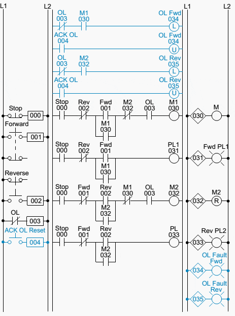
When it comes to controlling systems, a forward and reverse control circuit is an essential component. This type of circuit is used in many applications from factory automation to robotics, making its use extremely versatile. In this article, we’ll discuss what a forward and reverse control circuit is, how it works, and some of the different applications where it can be used.
A forward and reverse control circuit is essentially a series of components that allow an operator to switch between two states – forward and reverse. It includes a power source, two switches, two sets of power connections, and the two output states. The power source supplies voltage to each of the two switches, which then allows the user to select either the forward or reverse state. When the switch is in the forward position, the current will flow through one set of power connections and when the switch is in the reverse position, the current will flow through the other set of connections.
There are a variety of different applications where a forward and reverse control circuit can be beneficial, such as in factory automation systems, motors, robotics, and electric vehicles. The circuit is also perfect for applications requiring switching between two different speeds, directions, or powers. In addition, it can help conserve energy by shutting off the circuit when not in use.
When it comes to designing a forward and reverse control circuit, it is important to make sure all components are correctly wired and functioning properly. This can be done either manually or through software or circuit design tools. Having a comprehensive understanding of the parts and operations of the circuit will make it easier to troubleshoot any issues that may arise. Additionally, proper maintenance is essential to ensure the best performance of the circuit and the overall system.
In conclusion, a forward and reverse control circuit is an essential component in many applications - from motors to robotics. It allows for switching between two different states, and can help conserve energy by shutting off the circuit when not in use. Proper wiring of the components and maintenance of the circuit is necessary for optimal performance. With a few careful steps, your system can be running smoothly in no time.
Electrical Mechanical Info Forward Reverse Motor Control And Power Circuit Diagram Like Share Facebook
Nema And Iec Schematic Diagram Comparisons Mz081001en

Plc Implementation Of Forward Reverse Motor Circuit With Interlocking

Motor Circuits And Control Applied Electricity

Motor Forward And Reverse Direction Control Using Limit Switches

Plc Implementation Of Forward Reverse Motor Circuit With Interlocking

Plc Implementation Of Forward Reverse Motor Circuit With Interlocking

Ezgo Forward Reverse Switch Wiring Diagram Colored

The Circuit Diagram For Dc Motor Forward And Reverse Direction Scientific

Motor Forward And Reverse Direction Control Using Limit Switches

12v 24v Pwm Motor Controller Circuit Using Tl494 Irf1405
The Circuit Diagram For Dc Motor Forward And Reverse Direction Scientific

Forward Reverse Dc Motor Control Diagram With Timer Ic

Interlocking Methods For Reversing Control Basic Circuits

Ip4001 Datasheet Interpion Semiconductor Datasheetspdf Com

Forward Reverse Control
M J Electrical Engineering Junaid Three Phase Connection Reverse Forward Starter Controlling Diagram Facebook

Motor Control Circuits Ladder Logic Electronics Textbook
