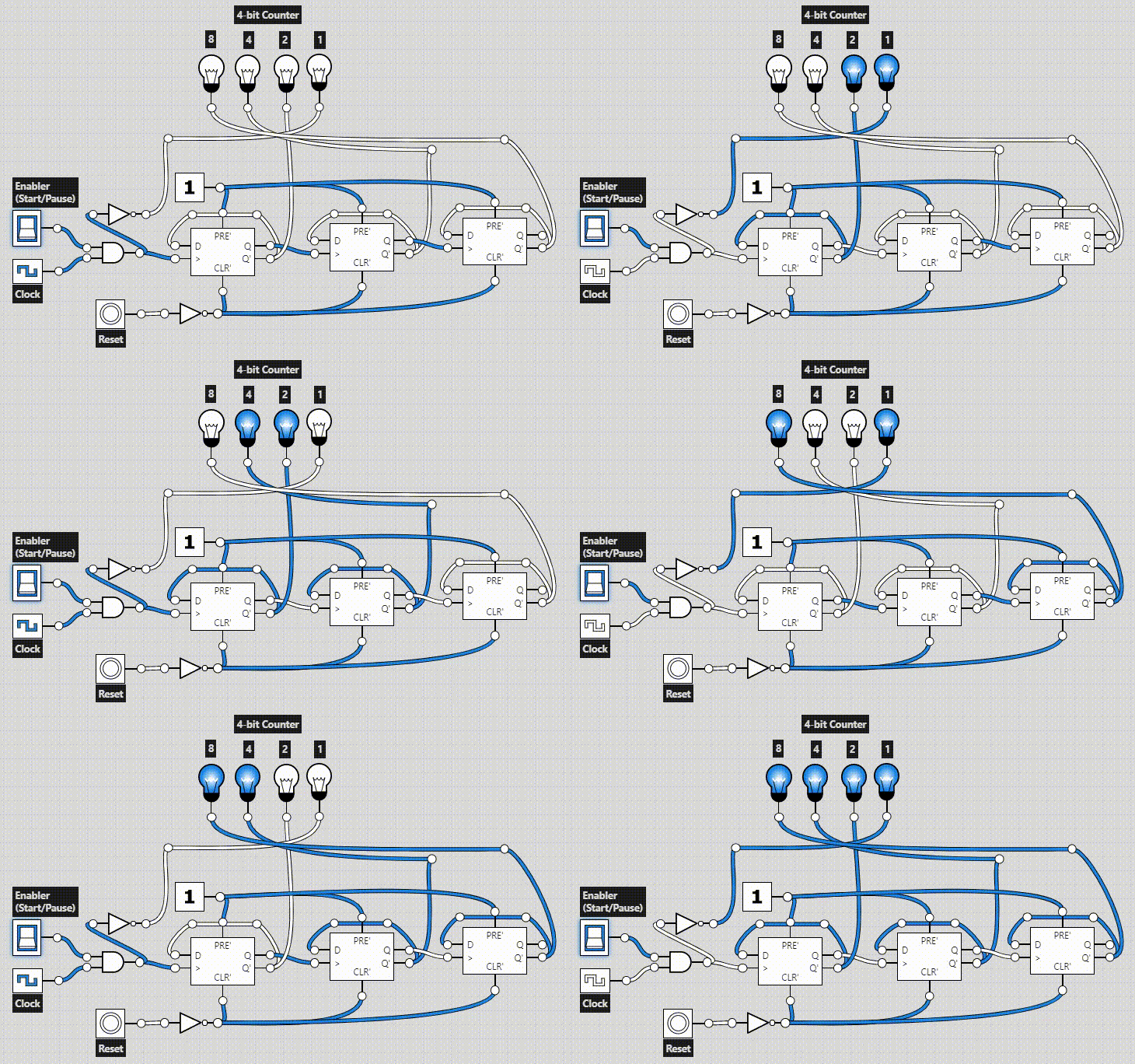
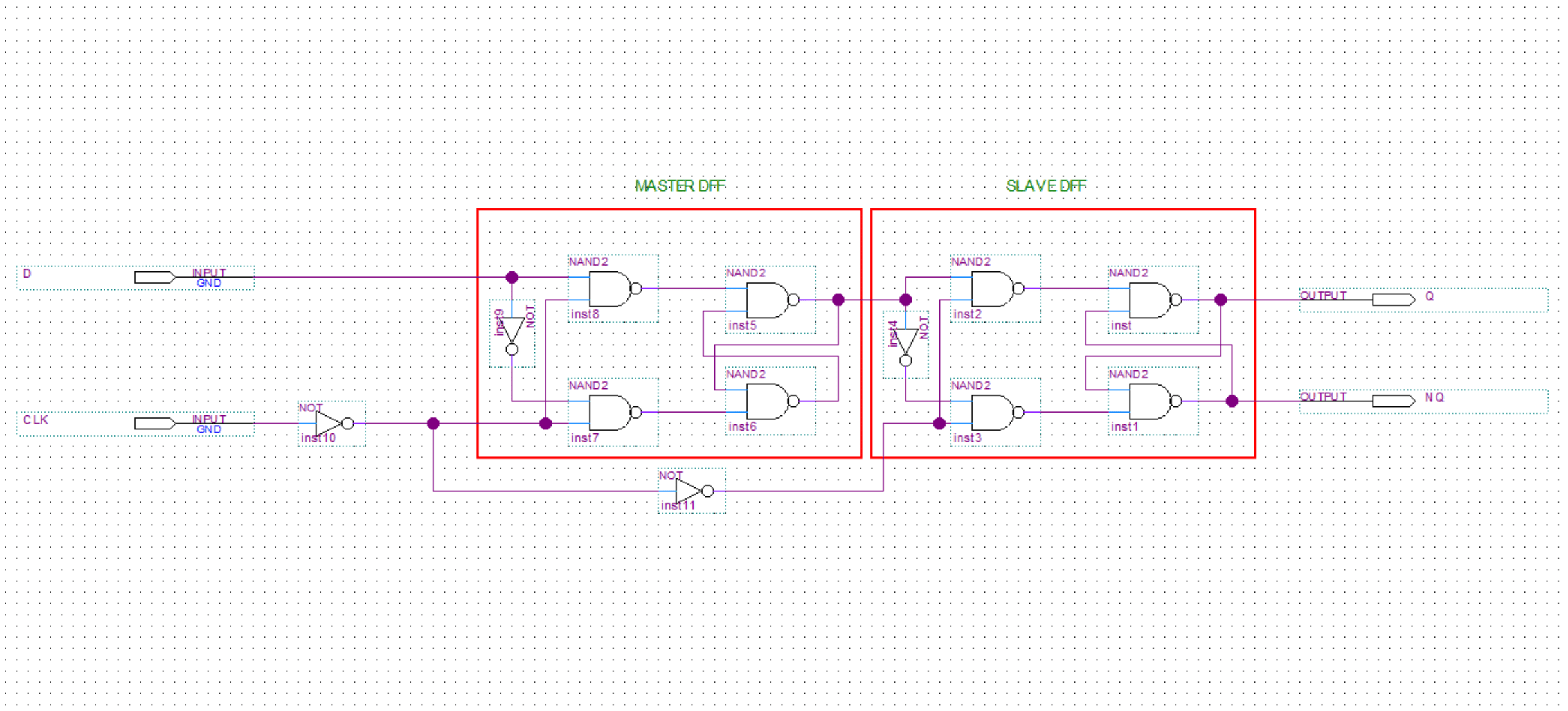
A D flip flop circuit diagram and truth table are essential tools for understanding and designing electronic circuitry. This type of flip-flop is used to store a single bit of data or signal, and has two stable states. It can be used to create complex circuits with multiple inputs and outputs that regulate electrical signals. D flip-flops are also useful for creating timers, counters, register files, and other memory functions.
A D flip-flop is a modified version of a JK flip-flop, which is the most common type of flip-flop. While a JK flip-flop has two input terminals (J and K), a D flip-flop has only one input terminal (D). When a signal is applied to the D terminal, the output is set to the value of the signal. This makes it easier to create multi-bit memories out of multiple D flip-flops.
The truth table of a D Flip Flop describes the various input/output combinations that result from its operation. For example, in a normal D flip-flop, when the input is low, the output is unchanged. Additionally, if the input is high the output is flipped from zero to one or from one to zero. By understanding the relationship between the inputs and outputs provided by the truth table, you can design and build complex memory elements and circuits.

Flip Flop Circuits Worksheet Digital

D Flip Flop Latch What Is It Truth Table Timing Diagram Electrical4u

Vhdl Tutorial 16 Design A D Flip Flop Using

Sr Flip Flop Circuit 74hc00 Truth Table

Flip Flop Truth Table Various Types Basics For Beginners
Solved Implement The D Flip Flop Circuit With Help Of Chegg Com

What Is D Flip Flop Circuit Truth Table And Operation

4 Bit Counter Using D Type Flip Flop Circuits 101 Computing

Flip Flop Truth Table Various Types Basics For Beginners

Solved 4 The Master Slave D Flip Flop Build Circuit On Chegg Com

D Type Flip Flop Circuit Diagrams In Proteus The Engineering Projects

T Flip Flop Circuit Using 74hc74 Truth Table And Working

D Type Flip Flop Truth Table

Realization Of Negative Edge Triggered D Flip Flop By Proposed Rdff Scientific Diagram

Jk Flip Flop What Is It Truth Table Timing Diagram Electrical4u

Flip Flop Truth Table Various Types Basics For Beginners

Jk Flip Flop Circuit Using 74ls73 Truth Table

How To Build A D Flip Flop Circuit With 4013 Chip

Edge Triggered D Flip Flop With Asynchronous Set And Reset Tutorial

Logic Circuitry Part 3 Pic Microcontroller
