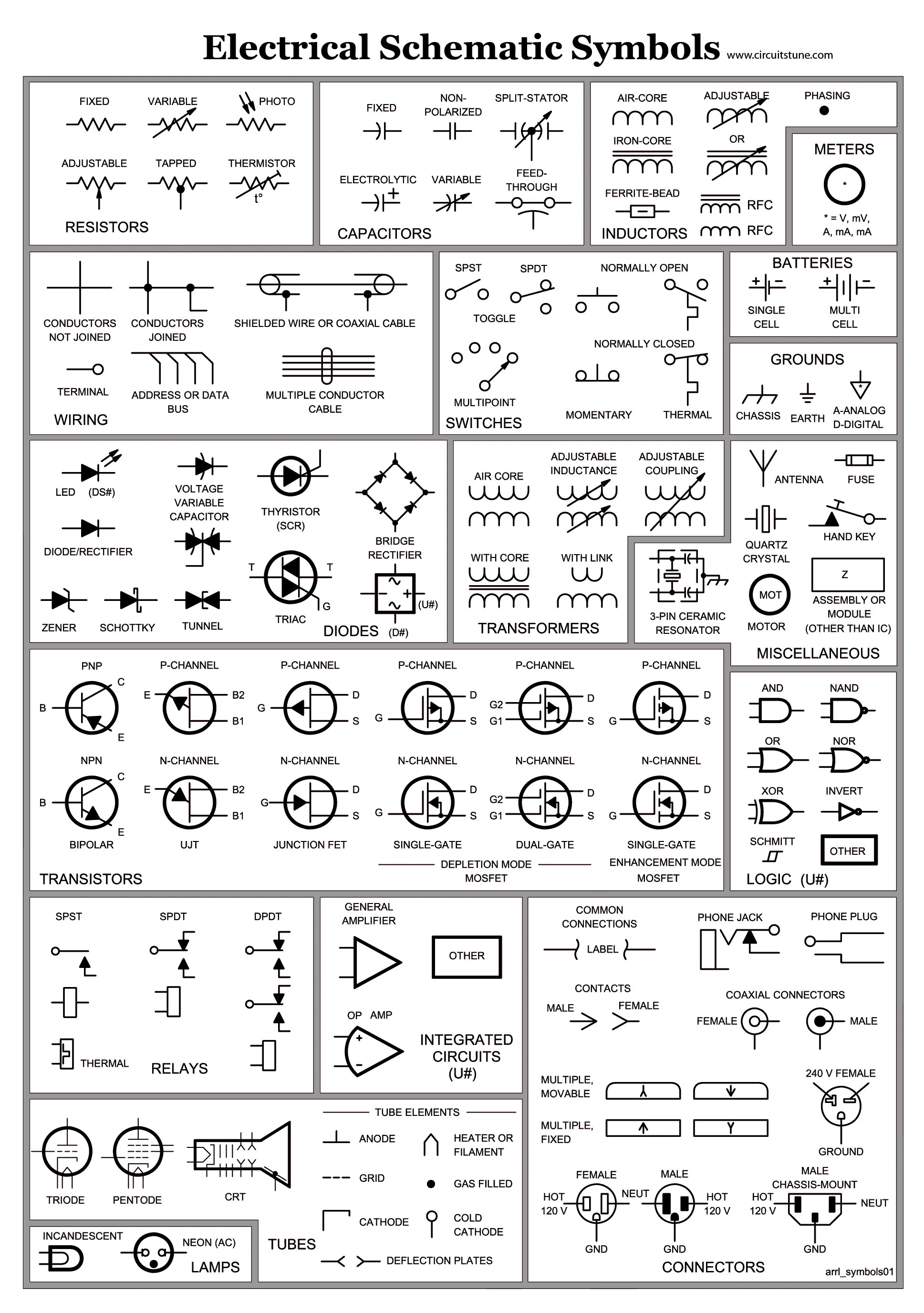
Control wiring diagrams are used to represent the behavior of a system or device. They can be described as “road maps” for troubleshooting problems and ensuring that the correct signals are sent to the various components of a system. Understanding control wiring diagrams is essential for anyone working with electrical systems, whether they be a professional technician in a factory setting or a DIY enthusiast in their home garage.
One of the key advantages of using control wiring diagrams is the variety of symbols used to depict various components and connections. Each symbol stands for an unique element of the system, giving technicians an easy way to understand how components interact. Typically, these diagrams use a standard set of symbols that have become widely accepted and used throughout the industry. Examples of these symbols include relays, switches, contactors, timer, transistors, diodes, and others.
Learning to read and interpret these symbols is a vital part of understanding how control wiring diagrams work. It is often said that a picture is worth a thousand words, and this is especially true when it comes to understanding complex electrical systems. Knowing how each symbol relates to its corresponding component greatly simplifies the process of troubleshooting and ensures that any problems can be identified and resolved quickly and accurately.

Contactor Operating Principle And Standards Learning Electrical Engineering

European Schematics Control Parts

Motor Control Symbols And Schematic Diagrams

How To Read Car Wiring Diagrams Short Beginners Version Rustyautos Com

Electrical Symbols Circuits

Wiring Diagrams Explained How To Read Upmation

Volvo 850 How To Use System Wiring Diagrams Volvotips

Ebook Automating Manufacturing Systems With Plcs

Electrical Symbols Diagram

Circuit Schematic Symbols Bmet Wiki Fandom

Common Electrical Symbols

Circuit Schematic Symbols Electronics Repair And Technology News

Electrical Symbols Integrated Circuit Wiring Diagrams With Conceptdraw Diagram Electronic Schematic

Wiring Diagram Symbols For Android

Types Of Electrical Schematic Symbols With Explanation At A Glance

Electrical Wiring Diagram Switches Symbols Automation Plc Programming Scada Pid Control System

Electrical Symbols Qualifying

Wiring Diagrams Explained How To Read Upmation

Automotive Wiring Diagram Symbols Basic Quizlet