Control Circuit Diagrams are used to design and build a variety of automated systems. They allow us to quickly and accurately construct complex processes, allowing machines and other devices to perform more effectively and efficiently. While the underlying concept is relatively straightforward – that of using diagrams to represent the flow of electricity – the real payment comes from understanding how to use the diagrams to create a functional system.
At their most basic level, Control Circuit Diagrams are composed of rectangles that represent components, lines that represent wires connecting components, and arrows that represent the flow of electricity. The components can be anything from levers and switches, to transistors and resistors. By studying the output of one or more components, it becomes possible to create complex systems that can work together to control the function of an entire machine.
To get a more in-depth picture of Control Circuit Diagrams, one can look into various topics such as the integration of logic elements, circuit design, reusability, simulation, and verification. With the right knowledge, those interested in designing and building systems can leverage these diagrams to their advantage. Not only can this technology save time and money, but with the right mental approach, it can also lead to interesting ideas and innovations within the industry.

Control Relay What Is A

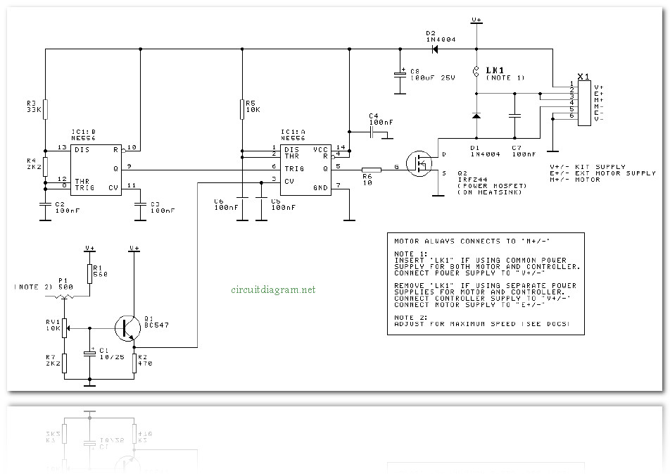
Dc Motor Sd Controller Circuit Using Ne555
Registered Master Electricians Of The Philippines Motor Control Language Electrical Symbols Words And Line Diagrams Provide Information Necessary To Understand Operation Circuits Together They Create

Dimmer Ac Motor Sd Controller Circuit Using Triac Electronics Area

The Schematic Diagram Of Control Circuit Scientific

Pwm Motor Sd Control Circuit With Diagram For Dc

Circuit Diagram Of The Digital Control System Scientific
Control Circuit Diagram Scientific

Dc Motor Sd Control Circuit Using Ic 555 Gadgetronicx

Dc Motor Sd Controller Electronic Schematic Diagram
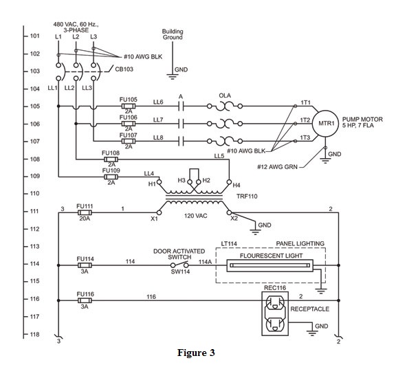
Wiring Diagram Of The Electric Circuit For Motor Control Scientific

This Is An Ir Remote Control Circuit Diagram For Chegg Com

Main And Auxiliary Circuit Diagrams Of Switching Three Phase Motors Via Contactor Directly Eep
Circuit Diagram Remote Control Unit Scientific

Electrical Panel Wiring Diagram

Motor Control Circuits Ladder Logic Electronics Textbook

2 Simple Infrared Ir Remote Control Circuits Homemade Circuit Projects

Schematics And Wiring Diagrams Circuit 1

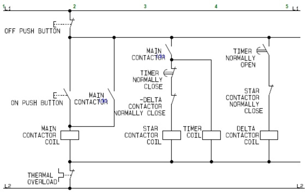
Using Star Delta Motor Control With Circuit Diagrams Turbofuture

A Condensed Guide To Automation Control System
