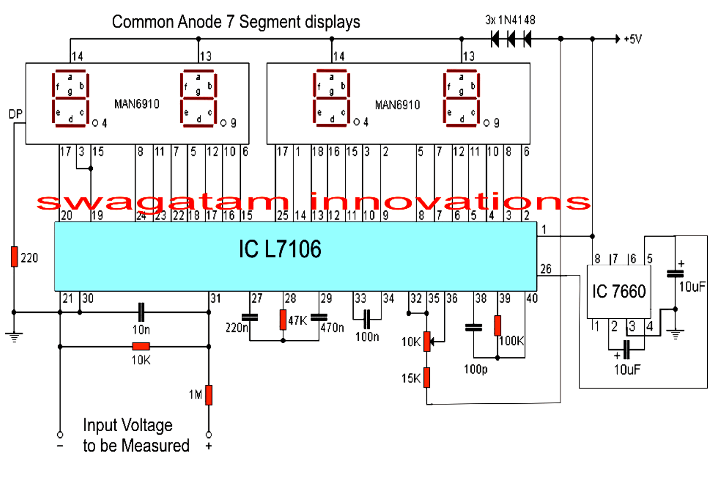
A voltmeter is one of the most essential devices when it comes to monitoring and troubleshooting complex electrical systems. A circuit diagram with a voltmeter helps technicians and engineers plot and document the electricity flowing through an electrical system so that potential problems can be identified and fixed more quickly.
Circuit diagrams are used to lay out the path between two or more components in an electrical system. The voltmeter, usually connected in parallel to the circuit, measures the voltage levels present in the system. The readings taken at each node in the circuit are then drawn on the circuit diagram, allowing technicians to gain a better understanding of the electrical environment and where issues might be occurring.
Circuit diagrams with a voltmeter allow technicians and engineers to identify where potential problem areas are in an electrical system by pinpointing the voltage readings at each node. These detailed diagrams can help make troubleshooting a system much faster, as they provide technicians with a visual representation of the way the electricity moves through the device. Additionally, the use of a voltmeter guarantees accuracy and precision when measuring voltage levels, meaning technicians can quickly and easily determine whether there is an issue with the electrical system.

What Is Voltmeter Voltmetertypes Uses Symbol Diagrams

Working Principle Of Voltmeter And Types Electrical4u

Fet Voltmeter Circuit

From The Circuit Diagram Shown Find Voltmeter Reading And Ammeter Study Com

Distinguish Between Ammeter And Voltmeter Class 12 Physics Cbse

Multimeter

Draw A Schematic Circuit Diagram Consisting Battery Plug Key An Ammeter And Bulb All Connected In Series With Voltmeter Parallel The Snapsolve

Voltmeter Circuit With Diagram And Schematics For Car Battery

Transpa Electricity Circuit Clipart Multimeter Symbols Schematic Hd Png Kindpng

An Ammeter And A Rheostat Are Connected In Series Voltmeter Is Scientific Diagram

An Ammeter And A Voltmeter Are Joined In Series To Battery Their Readings V Respectively If Resistor Is Now Parallel With The

Make Your Own Multimeter Dc Circuits Electronics Textbook

Led Voltmeter Circuit

Working Principle Of Voltmeter And Types Electrical4u

Eight Leds Make A 100 Division Voltmeter Edn

Simple Digital Voltmeter Circuit

The Electrical Circuit Consisting Of Connected Consumer A Bulb Voltmeter For Measuring Voltage And An Ammeter Cur In Stock Vector Adobe

18 2 Parallel Circuits Series And Siyavula

Electronic Voltmeter Working And Block Diagram Electrical Academia