Circuit Diagram Of 5V Relay – An Essential Tool for Automation Projects
The circuit diagram of 5V relay is an essential tool for any home automation projects. It allows users to control electrical items such as lights, appliances, and more. This circuit is used to connect various devices to a single source of power and then provide an output that can be controlled from a remote location. By using this circuit, you can switch on and off items in your home without having to manually do so each time.
Relays are installed in the circuit between the electrical device and the main power source. They act as a bridge between the two, allowing the user to control the device without having to take care of the wiring or other components. The circuit diagram of the 5V relay is fairly simple and easy to understand. It is composed of five main parts, including the base, the contacts, the shunt, the coil, and the diode. All these components work together to ensure that the device receives the correct voltage and is able to function properly.
The base and contacts of the relay provide the connection point where electricity enters the circuit. Once the current is sent to the coil, it is converted into a low-voltage electrical signal which enables the shunt to break the returns path. The diode in the circuit protects the device from short circuits, which may occur if there is too much voltage running through the circuit. The coil also provides a return path for the excess current produced by the relay.
With a circuit diagram of 5V relay, you can easily control the amount of power sent to each of your appliances. This makes it easier to adjust the level of light and other settings in your home, without worry about overloading individual devices. In addition, this circuit can be used to safely set up safety devices such as sensors and alarms. All these features make the circuit diagram of 5V relay an essential tool for any home automation project.

1 Channel 5v Solid State Relay Module Wiki

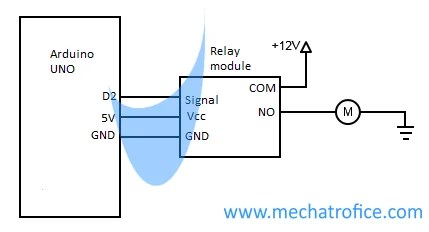
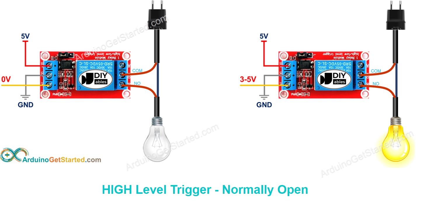
Arduino Relay Module Connection Tutorial

5v Single Channel Relay Module Pin Diagram Specifications Applications Working

Microcontroller 12v Relay Circuit Converted To 5v Under Uc Control Repository Circuits 25827 Next Gr

Simple Short Circuit Protection Diagram

Arduino Relay Tutorial

Auto Shut Off Overvoltage Protection Circuit Using A 5v Spdt Relay

Stage 4 Complete Beginner S Guide For Arduino Hardware Platform Diy Codeproject

5v Relay Pinout Description Working Datasheet

عادي سحق العاصفة Arduino Relay Circuit Nmpsaoluis Com

Arduino Relay Tutorial

Simple Relay Switch Circuit Diagram

Low Voltage Relay Driver Circuit Diagram

5v Single Channel Relay Module Pinout Working Interfacing Applications

Working 5v Relay Module For Mc Easyeda Open Source Hardware Lab

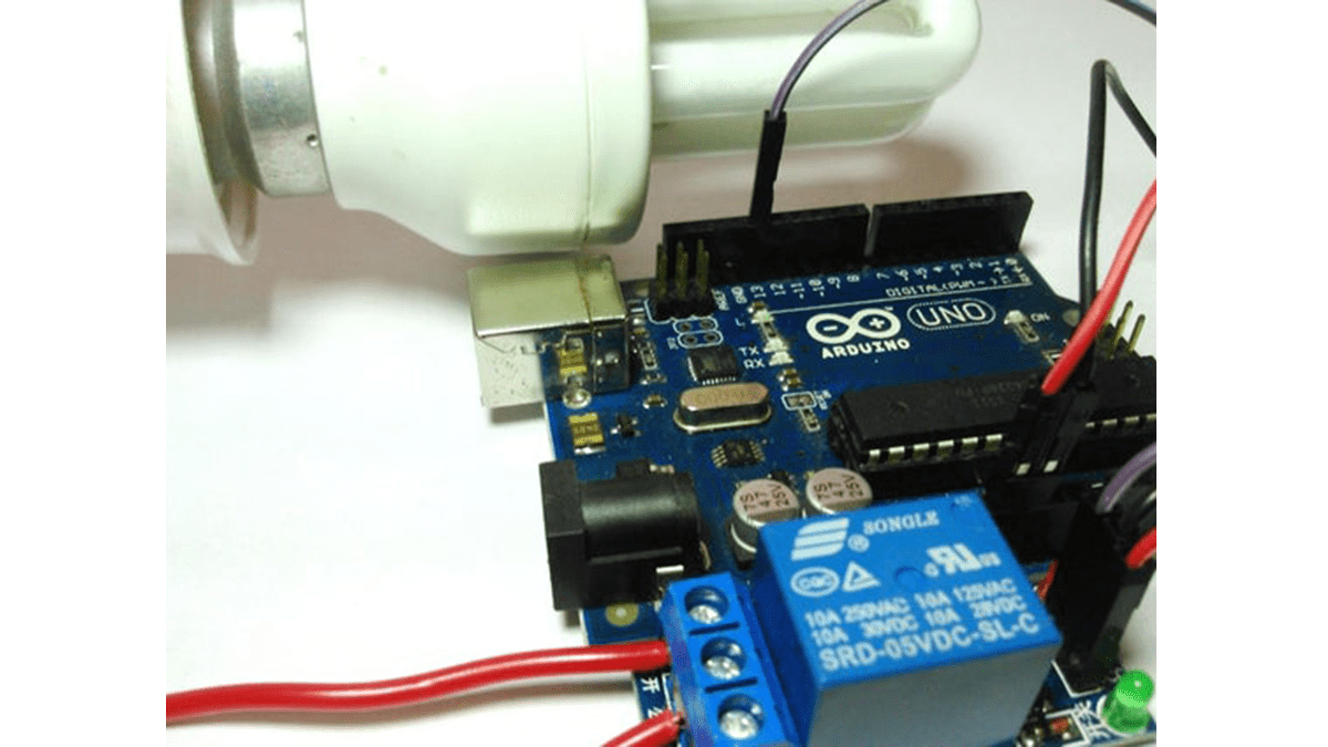
Control Your Home Appliances Using Arduino And Relay

Arduino Autoshutdown Using 5v Dc Relay Or Mosfet Project Guidance Forum

Ks0011 Keyestudio 5v Relay Module Wiki