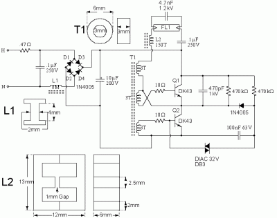
CFL light circuit diagram is one of the most flexible, efficient, and commonly used forms of lighting today. It is a safer, more energy-efficient alternative to traditional lighting and has a wide range of applications. Whether for the home or industrial use, CFL (compact fluorescent) light circuit diagrams can be designed to meet specific requirements and provide unique lighting effects.
CFL light circuit diagrams are composed of various components, including ballasts, lamps, sockets, capacitors, switchgear, and wiring. Each of these components comes together to create the perfect lighting solution. The ballast is often the most important part of the circuit diagram, as it controls the amount of electricity that reaches the lamp, and ultimately affects the intensity and colour of the light that is produced. Ballasts come in different wattages and voltage ratings, dependent upon the type of lamp used.
The lamps, or light bulbs, also have an important role to play in the CFL light circuit diagram, as they are responsible for the actual illumination of the interior space. The choice of lamps depends on the wattage being used, and the number of lamps per circuit. Different bulbs can be used to achieve varying effects, ranging from soft to bright lighting. Further, the wattage and bulb type also play a role in determining the optimal temperature of the space.
Finally, the wiring and switchgear used in the circuit diagram should also be chosen carefully. Safety is always the most important consideration when creating a lighting system, so all electrical components must be easily accessible and safe to operate. All wiring should be properly insulated, and all switches should be clearly labeled so that no mistakes are made.
Overall, CFL light circuit diagrams offer a variety of lighting solutions which are both cost-effective and efficient. With proper knowledge and design, homes and businesses alike can benefit from the energy-saving effects of CFLs. When considering a lighting solution, take the time to consider all components that will be used in the CFL light circuit diagram, and be sure to use the right parts for your application.

How Compact Fluorescent Lamps Work And To Dim Them Eetimes

50w Inverter 12vdc To 220vac Electronic Schematic Diagram
Modified Energy Efficient Compact Fluorescent Lamp

A Simple Led Lamp Circuit From S Uses 5 And Takes Only 50 Ma

Power Factor Correction Of Compact Fluorescent And Tubular Led Lamps By Boost Converter With Hysteretic Control

Eec247 Information On Compact Fluorescent Lighting

Fluorescent Circuit Page 3 Light Laser Led Circuits Next Gr

Typical Compact Flash Lamp Ballast Circuit 10 15 Fluorescent Scientific Diagram

Difference Between Cfl Led Bulbs With Comparison Chart Circuit Globe

Low Loss Power Supply Of Solar Powered Light Circuit Diagram Seekic Com
Ac Powered Pir Light Circuit Soldering Mind

Typical Compact Flash Lamp Ballast Circuit 10 15 Fluorescent Scientific Diagram

Ultra Bright Led Lamp Circuit Diagram

Fluorescent Circuit Page 4 Light Laser Led Circuits Next Gr

12v Cfl Inverter Circuit Simple Diagram

Application Notes And Circuits For Irplcfl2 42 Watt Compact Fluorescent Ballast Reference Design

How Cfl Works Compact Electronic Ballast

Power Factor Correction Of Compact Fluorescent And Tubular Led Lamps By Boost Converter With Hysteretic Control