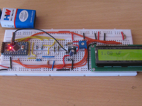
Capacitance measurement circuit diagrams are a critical tool that is used to accurately measure the capacitance of electronic components in circuits. With the widespread use of modern electronic devices, capacitors are used in virtually every system and application from home electronics, automotive systems, and industrial automation to medical equipment and military applications. The ability to quickly, accurately, and reliably measure capacitance is an essential part of designing, repairing, and maintaining these complex systems.
The typical capacitance measurement circuit diagram consists of three main elements - a resistive network for current measuring, a voltage source to supply the measured capacitance, and a bridge amplifier to compare the measured current to a reference current. The resistive network is typically composed of resistors and other components that can be used to generate the required current for the test. The bridge amplifier is responsible for comparing the measured current to the reference current, and it provides the necessary signal to indicate the capacitance.
Finally, the voltage source supplies the necessary voltage to the circuit. This is usually done by using an AC voltage source, either a DC voltage source or an AC-DC converter. Once the voltage is chosen, it is then applied to the circuit while the capacitance is being measured. The measured currents are then compared and the values obtained from the bridge amplifier indicate the capacitance value. With the proper test equipment, the accuracy of the measurements can be easily determined.
By using the right combination of components and voltage sources, a capacitance measurement circuit diagram can provide the most accurate results. This is why it is so important to understand all the components that make up a capacitance measurement circuit and how they work together. By mastering this knowledge, designers, technicians, and engineers can confidently create reliable and accurate capacitance measurement circuits that are capable of delivering accurate results.

Simple Esr Meter Circuit Diagram

Capacitance Measurement Using Arduino

Capacitance Meter

Esr Meter

Schematic Circuit Diagram Of The Capacitance Measuring System Scientific

2 Simple Accurate Capacitance Meter Circuits

Simple Capacitance Meter Bins Parts Edn

Equivalent Series Resistance Meter

Water Level Measurement Circuit Under Liquid Sensing Circuits 14101 Next Gr
Considerations When Switching Low Capacitance Measurements Ni
Lcr Meter Analog Front End Reference Design Rev B

Electronic Circuit Schematic For Capacitance Meter Free On The Internet
Improve Resistance Measurement Accuracy With 6 Wire Technique Ni

Capacitance And Inductance Meter With Digital Ics

2 Simple Capacitance Meter Circuits Explained Using Ic 555 And 74121 Homemade Circuit Projects

Application Note An 016 Probes Probing Teledyne Lecroy

Sensors Free Full Text Measurement Of Water Holdup In Vertical Upward Oil Ndash Two Phase Flow Pipes Using A Helical Capacitance Sensor Html

Capacitance Meter Electrical4u

How To Build Capacitance Meter Circuit Diagram

Use Analog Techniques To Measure Capacitance In Capacitive Sensors Electronic Design

