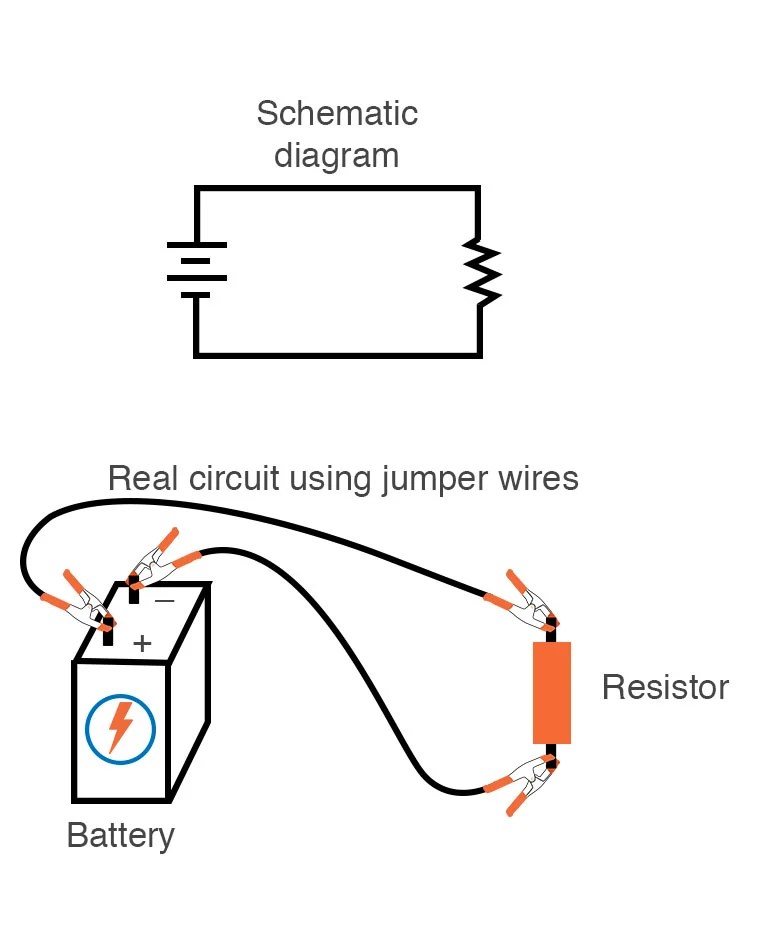
Circuit diagrams are the building blocks of electrical engineering. They are used to create physical connections between components for power delivery and signal routing. A basic circuit diagram uses pictorial symbols to represent various types of electrical components, such as resistors, capacitors, and transistors, as well as a variety of wires and connectors. This allows engineers to quickly visualize how the components interact with one another, allowing them to identify potential problems in the design or implementation of the circuit.
The first step to understanding a basic circuit diagram is to become familiar with the symbols used. Each component has its own unique symbol, and it is important to be able to recognize these symbols in order to read and interpret a circuit diagram accurately. Once the symbols have been learned, it becomes easier to understand how the components interact. The relative positions of the components also help to provide an indication of the type of relationship that exists between them.
The second step is to familiarize oneself with the couple of rules labeled Ohm’s law and Kirchhoff’s law. These two laws provide the backbone for most of the analysis of electrical circuits. They are based on the concept of how current flows through components and how it changes relative to voltage, resistance, and other factors. By mastering these fundamental concepts, one can use a basic circuit diagram to evaluate the performance of a circuit and troubleshoot any errors or issues.
Understanding basic circuit diagrams is the foundation of any electrical engineering project. With a little bit of practice, one can quickly become accustomed to the various symbols used, as well as the fundamental principles governing circuit operation. This knowledge will help engineers to quickly design, build, and debug circuits with greater confidence.

4 Basic Pneumatic Circuits Power Motion

What Is An Electrical Circuit Codrey Electronics

Simple Relay Switch Circuit Diagram

Simple Electronic Circuits For Beginners And Engineering Students

Basic Amplifier

Physics Tutorial Circuit Symbols And Diagrams

Basic Pneumatic Circuits Tech Briefs

How To Read Electrical Schematics Circuit Basics

L2 Circuit Schematics Physical Computing

Simple Electrical Circuits

Basic Circuit Diagram Of An Electric Rice Cooker Scientific

Resources

Circuit Symbols Of Electronic Components Electrical Symbol

Basic Circuit Diagrams Solution Conceptdraw Com

How To Read A Schematic Learn Sparkfun Com

How To Read A Schematic Learn Sparkfun Com

Electric Circuit Diagram Images Browse 17 972 Stock Photos Vectors And Adobe

Building Simple Resistor Circuits Series And Parallel Electronics Textbook