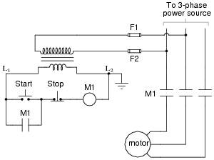
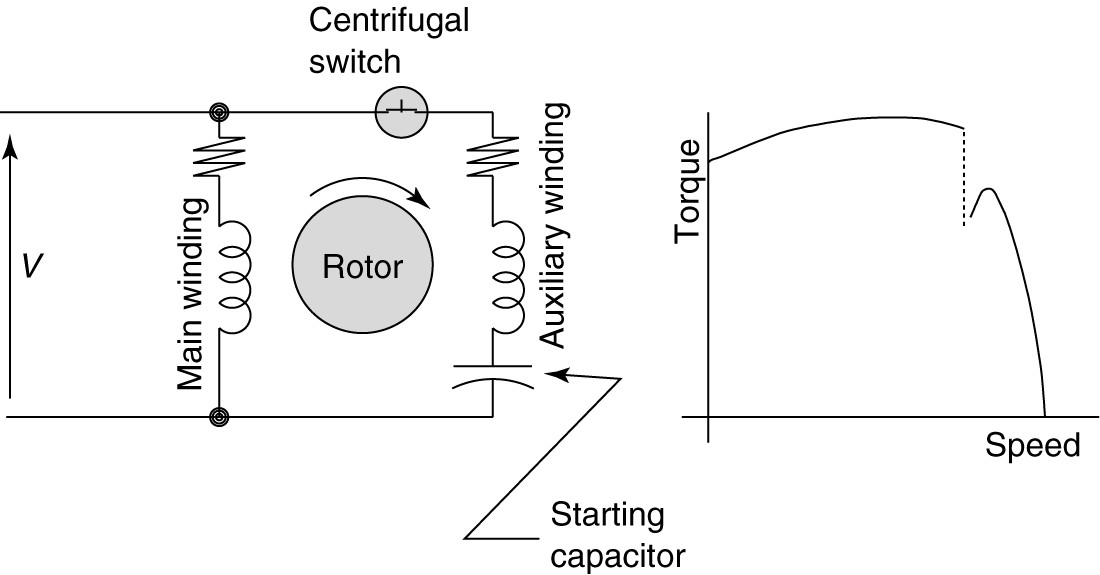
The wiring diagram of an AC motor is an integral part of any motor installation. This diagram shows the various parts and components in the circuit, including the power source, the motor controller, the motor itself, and the output devices. It also provides other important information, such as insulation requirements, current ratings, and temperature ranges.
Without a properly setup AC motor circuit wiring diagram, a motor repair technician cannot accurately diagnose and repair problems with the motor system. Similarly, an experienced electrician can use the diagram to ensure they are wiring the motor correctly and understand the safety requirements before connecting it to the power grid.
If properly maintained and serviced, AC motors can last well over 25 years without showing any sign of wear. Understanding and using the AC motor circuit wiring diagram can help keep your motor performing at its peak and minimize its downtime. Having an accurate and up-to-date wiring diagram is essential for an efficient and safe motor installation, so be sure to always use the latest version.

Motor Controller Electric Electrical Wires Cable Wiring Diagram Vehicle Png 760x536px

Show Tell Ac Induction Motors

Easiest Way To Reverse Electric Motor Directions Robot Room

Ac Capacitor Wiring Diagram And Connection Procedure Etechnog

Motor Control Circuits Types Electrical Automation Plc Programming Scada Pid System

Ac Motor Basic Stator And Rotor Operation Diagrams

Figure 2 8 12v Electric Motor Tester Circuit Wiring Diagram M983

Ac Motor Control Circuits Worksheet Electric

Electrical And Electronic Drawing Controls

Types Of Single Phase Induction Motors Motor Wiring Diagram Electrical Academia

No 13 Winding Diagram For An Ac Motor Simulation Technology Electromechanical Design Jmag

Air Conditioner Motors
Electrical Technology Wiring Diagram Of Split Phase Single Induction Motor In A Ceiling Fan Capacitor Tutorial Https Www Electricaltechnology Org 2019 11 Replace Html Facebook

How To Wire Motor Sd Or Direction Controller Huimultd

Circuit Diagram Of Induction Motor Connected To An Inverter Scientific

Capacitor Start Motors Diagram Explanation Of How A Is To Single Phase Motor Bright Hub Engineering

Stepper Motor Wiring Diagram Circuit Electrical Wires Cable Electronic Png 1559x1170px

How To Wire Motor Sd Or Direction Controller Huimultd

Wiring Diagram Electrical Wires Cable Electric Motor Others Angle Text Png Pngwing

Electrical Diagram For A Csir Motor
