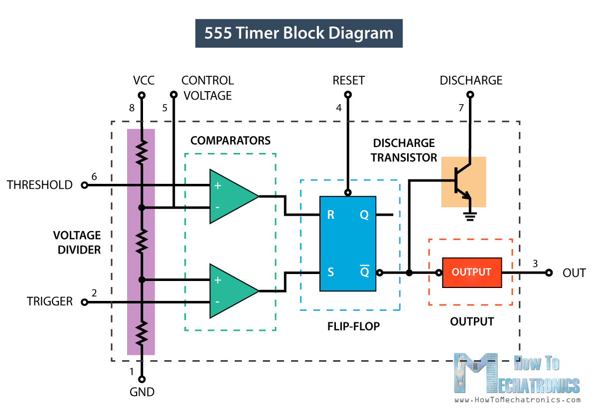
555 Timer Pin Diagram Description is a valuable tool for anyone looking to understand the functionality of the timer. It's a diagram that helps visualize the pins and their corresponding connections to form the timer circuit. This is an incredibly useful tool for those who want to learn more about the functionality of the timer, as it clearly outlines the connections as well as the functions of each pin.
The diagram itself is incredibly easy to interpret. The diagram displays the main components of the timer in the center, with various pins surrounding it. Each pin on the diagram has a specific function, such as input or output signal, enable, reset, power, and more. This makes it much easier to understand how all the various pieces work together when forming the timer circuit. Additionally, it's much easier to make any necessary adjustments to the circuit since you're able to easily identify the pins and what their purpose is.
Overall, the 555 Timer Pin Diagram Description is incredibly helpful for anyone who wants to fully understand the workings of the timer. The diagram makes it easy to identify the pins and their respective functions. This makes it easy to adjust the timer circuit, making it much easier to get the desired result. For anyone wanting to get more out of their timer circuit, this diagram is an invaluable tool.

How Does Ne555 Timer Circuit Work Datasheet Pinout Eleccircuit Com

555 Timer Ic Block Diagram Working Pin Out Configuration Data Sheet

555 Timer Ic Pinout Diagrams Features Operating Modes Description Datasheet

Automatic Street Light Project 555 Timer

Pin Configuration Of The 555 Timer

Ic 555 Timer Pin Daigram With Configuration And It S Applications

555 Timer Basics Application Notes

555 Timer Ic Working Principle Block Diagram Circuit Schematics

555 Timer Pinout

555 Timer Ic Introduction Basics Working With Diffe Operating Modes

Making Of Flashing Blinking Led Circuit Diagram Using 555 Timer Ic

5 20 Minuts Timer Circuit Using Ic 555 Eleccircuit Com

555 Timer Ic Block Diagram Working Pin Out Configuration Data Sheet

555 Timer Ic Pin Diagram Working Features Uses Envirementalb Com

555 Timer Ic Block Diagram Working Pin Out Configuration Data Sheet

Ale Multi Using 555 Timer

555 Timer Monole Circuit Calculator Electrical Engineering Electronics Tools

Led Flasher Circuit Diagram With 555 Timer Ic

555 Timer Ic Internal Structure Working Pin Diagram And Description