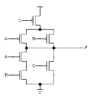
The world of electrical engineering is full of complex diagrams and designs. One of the most important is the 3 input XOR gate CMOS circuit diagram. This diagram is essential in designing digital circuits and is widely used across many industries.
To use the 3 input XOR gate CMOS circuit diagram, it's important to understand how it works. At its core, a typical XOR gate has two inputs and one output. It's an important logic function that allows for the combining of two signals into one value. In the case of the 3 input XOR gate CMOS circuit diagram, it adds another level of complexity given its three inputs. By adding an extra variable, the user can effectively combine three signals into one output.
Given the complexity of the 3 input XOR gate CMOS circuit diagram, it's important for users to be aware of all the factors that go into it. To that end, the user must understand voltage levels, timing constraints, noise immunity, and power consumption. All of these factors must be taken into account for the design to achieve optimal performance. Additionally, proper implementation of the 3 input XOR gate CMOS circuit diagram requires knowledge of CMOS technology, making it ineffective for those without the necessary expertise.
Overall, the 3 input XOR gate CMOS circuit diagram is an incredibly versatile and valuable tool in the area of electrical engineering. With its ability to add an extra level of complexity to electrical design, this diagram is essential in numerous applications. However, it’s important to remember that its implementation requires a comprehensive understanding of CMOS technology as well as other important related factors. By properly considering these, users will be able to make the most of this powerful tool.

Bipolar Xor Gate With Only 2 Transistors Details Hackaday Io

Cmos Xor Gate Circuit Diagram Scientific

Logic02 Gif

Layout Design Analysis Of Xor Gate By Using Transmission Gates Logic Ijeee Elixir Publications Issuu

Cmos Based Carbon Nano Pass Transistor Logic Integrated Circuits Nature Communications
4 Basic Digital Circuits Introduction To

Solved Chapter 1 Problem 8e Solution Cmos Vlsi Design 4th Edition Chegg Com
4 Basic Digital Circuits Introduction To

How To Design Xor Gate Using Mosfet Quora
Homework Solution For Chapter 1
Mc74lcx86 Low Voltage Cmos Quad 2 Input Xor Gate

Bipolar Xor Gate With Only 2 Transistors Details Hackaday Io

Circuit Design Of The Proposed 3 Transistor Xor Gate Scientific Diagram

Mc74vhct86a Quad 2 Input Xor Gate Cmos Logic Level
How Many Transistors Are In A 3 Input And Gate Quora

Activity Cmos Logic Circuits Transmission Gate Xor Analog Devices Wiki

The Circuit Topology Of New Dscl Gate A 2 Input Xor Xnor Scientific Diagram
Homework Solution For Chapter 1