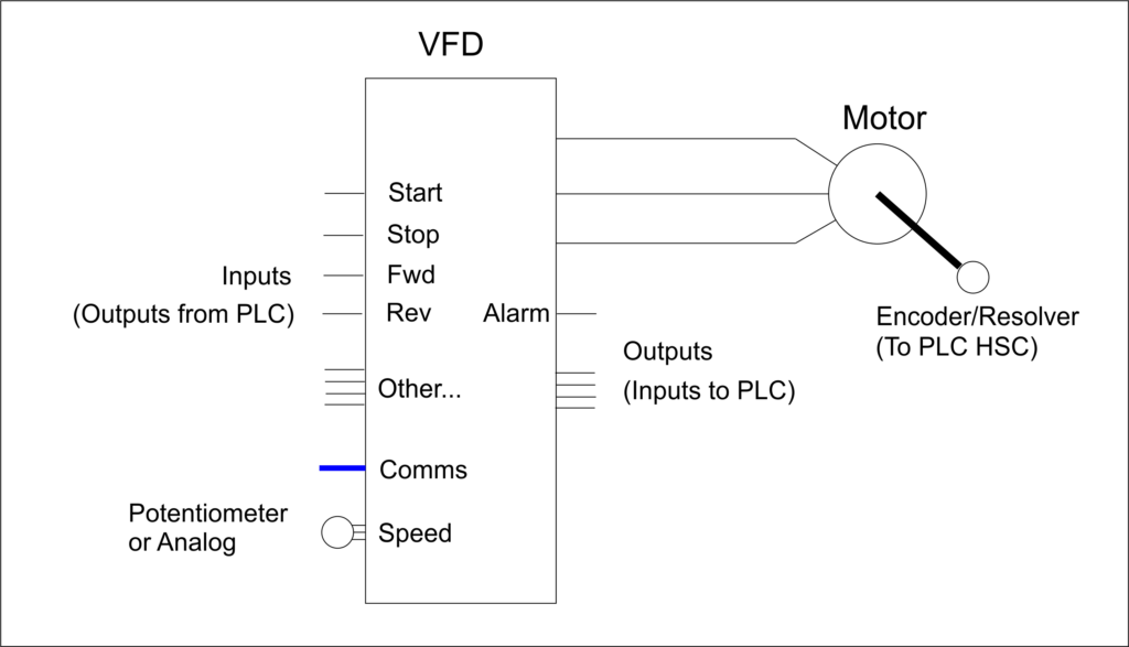
VFD Control Wiring Diagrams are a critical component of modern electrical systems, providing the necessary means to control the supply of power to various parts of a building or facility. This type of diagram is increasingly more important as efficiency and safety regulations become more stringent for industry.
Using a VFD Control Wiring Diagram, an engineer or technician can easily map out the correct course of action when performing electrical installations and repairs. This includes determining the correct type of wiring to use, and also accounting for system load requirements. As such, these diagrams are extremely useful in cutting down on time, labor, and cost associated with a project.
With the appropriate attention to detail, VFD Control Wiring Diagrams can provide an easy-to-understand visual aid that helps any professional install and maintain an effective electrical system. The ability to comprehensively inspect and diagnose problems quickly and accurately can make a huge difference in terms of how efficiently, efficiently, and safely a job can be completed. Keeping up with the ever-evolving standards in this field, it's essential for anyone involved in the repair, installation, or maintenance of the electrical infrastructure to have some experience with VFD Control Wiring Diagrams.
Ace Variable Frequency Drive System

What Is A Vfd Drive And Why You Need One Br Automation Control Systems

Plc Drive Vfd Control Automationprimer

Vfd Start Stop Wiring Diagram Electrical4u

Solid State Circuits For Variable Frequency Drives

Learn How To Use Plc And Vfd For Pump Control Power Circuits Analysis Eep

Vfd Start Stop Wiring Diagram Electrical4u

Warco Gh18 Mill With Vfd Wiring Diagrams Model Engineer

Sawmill Creek Woodworking Community

Practical Course To Wiring And Setting Parameters Of Variable Frequency Drives Vfds Eep Academy Courses

1 Vfd 2 Motors

Saftronics Pc10 Basic Wiring Diagram

Working Of Variable Frequency Drive Vfd Or For Motor Control Electrical Automation Plc Programming Scada Pid System
Vfd Wiring Page 3 Home Model Engine Machinist Forum

Vfds Probotix Wiki

Vfd Wiring Instructions Add Ons Modifications Sienci Community Forum

Controlling 3 Phase Induction Motor Using Vfd And Plc

Vfd Start Stop Wiring Diagram Electrical4u