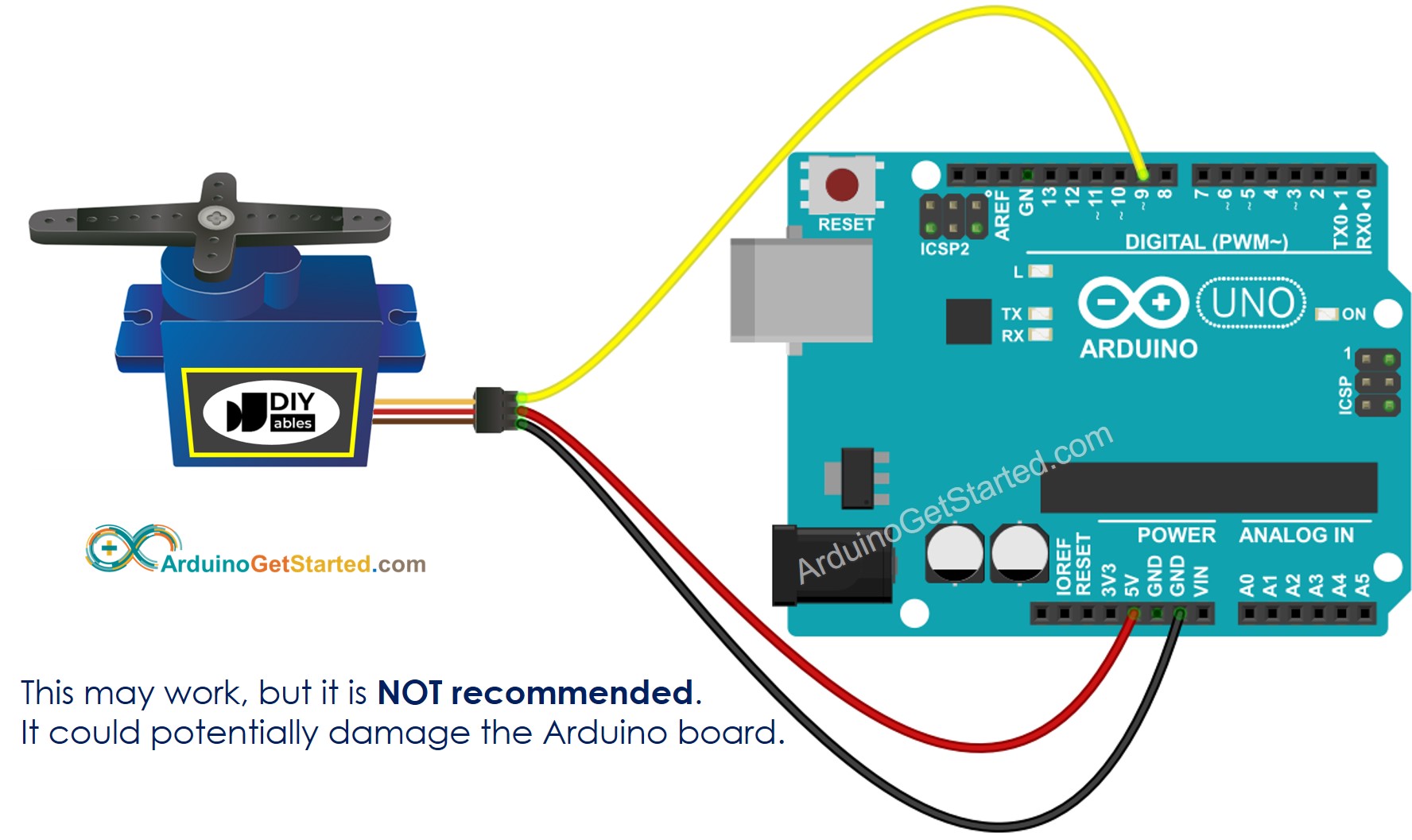
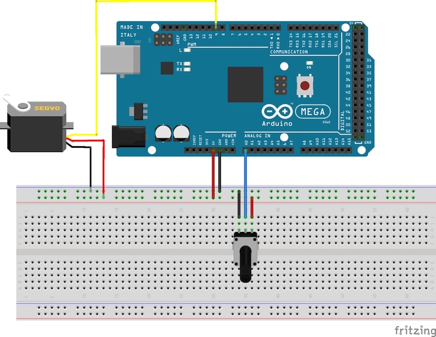
Servo Motor Schematic is an important component of any electrical circuit. It’s a small but powerful machine that controls the direction and speed of motors, making it one of the most important components within electrical circuits. In order to maximize efficiency and minimize wear and tear, Servo Motors must have the right schematic drawing.
The design of a Servo Motor Schematic is critical for optimal performance. It has two main components - the mechanical portion and the electrical portion. The mechanical portion consists of the motor itself, along with the gears, shafts, and other components that allow it to rotate in a specific direction. The electrical portion consists of the connections between the power source, the motor, and the sensors that control the movement. In some instances, additional components such as limit switches may be included in the schematic.
A successful Servo Motor Schematic allows for error-free operation, so it’s essential to understand the basics of designing a schematic. First, the necessary components must be identified and connected accurately, followed by testing to ensure proper operation and performance. A comprehensive testing procedure is necessary before the schematic is used in an actual application. Finally, the schematics must be checked against the specifications and safety guidelines to ensure maximum performance and safety. With the right Servo Motor Schematic, a powerful and efficient motor can be implemented within any electrical or electronic system.

Servo Motor Basics With Arduino Doentation

Schematic Diagram Of Mini Servo Motor With Arduino Mega In Main Circuit Scientific

Servo Motor Systems Worksheet Analog Integrated Circuits

Arduino Servo Motor Tutorial

Getting Servo Motor And Drive Phase Commutation Alignments Right

How Servo Motor Works Interface It With Arduino Last Minute Engineers

Servo Motor Control Schematic Pyroelectro News Projects Tutorials

Servo Motor Control With An Arduino Projects

What Is A Servo Motor How Works Control Ettron

Dc Servo Motor Characteristics And Its Applications

Arduino Servo Control Schematic Pyroelectro News Projects Tutorials

Arduino Servo Motor Basics And Control Maker Portal

How To Control Servo Motors With Arduino Complete Guide

Servo Motor Driver Circuit Using Ic 555 Gadgetronicx

The Breadboard Layout For Sweep Arduino Lesson 14 Servo Motors Adafruit Learning System

Robot Platform Knowledge How Servo Works

Servo Motor Controller Using 555 Ic

Dc Servo Motors Theory Of Motor Electrical4u

How To Control Servo Motors With Arduino 3 Examples

Servo Motor Driver Circuit