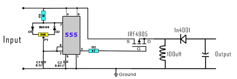
A buck-boost converter, also known as a step-up-step-down converter, is an electronic circuit that can raise or lower the voltage of a power source. It is one of the most common types of dc-to-dc converters, and is used to supply electrical components with the correct amount of power. A schematic of a buck-boost converter consists of four main components: a switch, inductor, capacitor, and diode.
The switch is typically a metal-oxide-semiconductor field-effect transistor (MOSFET), which controls the flow of electricity in and out of the converter. The inductor stores energy while the current is switched by the MOSFET, ensuring that there is a continuous flow of electricity even when the switch is open. The capacitor smooths out any voltage ripple, or fluctuations in voltage, that occurs when the switch is closed. The diode allows current to flow only in one direction, thereby regulating the power output of the converter.
Buck-boost converters are widely used in modern electronics, particularly in applications such as portable electronic devices, solar power systems, and electric vehicles. Their ability to efficiently and accurately reduce or increase voltage levels makes them ideal for supplying devices with the power they require and preventing damage caused by overvoltage. In addition, their compact size and low cost make them suitable for a range of applications.

Buck Boost Dc Converter Imperix

Buck Boost Circuit Using Ic 555 Homemade Projects

Single Ic Converter Operates Buck And Boost To Provide An Output That Is Within The Input Voltage Range Analog Devices

Buck Boost Converter With Pic Microcontroller And Ir2110

Usb To 12v 9v Buck Boost Converter Circuit Gadgetronicx

Regulated Buck Boost Dc Converter Circuit Electronics Projects Circuits

Boost Converter Circuit Using Uc3843 Soldering Mind

Solved 1 A Buck Boost Dc Converter Schematic Is Shown Chegg Com

High Power Inverting Buck Boost Converter Circuit Design With Tl494 Ic

Design Of Pcm Cot Buck Boost Converter With Dynamic Adjule Output Voltage Ee Times Asia

A Novel Approach To Creating High Efficiency Simple Buck Boost Converter Edn

Dc To Buck Boost Converter Circuit Homemade

Buck Boost Converter What Is It Formula And Circuit Diagram Electrical4u

The Schematic Of Voltage Controlled Buck Boost Converter Scientific Diagram

Dc To Buck Converter Tutorial Diagram Maxim Integrated
Buck Boost Converter Circuitlab

How Buck Boost Circuits Work Homemade Circuit Projects

Dc To Converter Circuits Using Sg3524 Buck Boost Designs Homemade Circuit Projects

Schematic Of Buck Boost Dc Converter With Variable Source Voltage Scientific Diagram