Schematic diagrams are an invaluable tool for electrical engineers. These comprehensive drawings provide a visual representation of how a circuit is wired and how the components interact. They can serve as a troubleshooting guide, helping engineers pinpoint complex problems in a shorter amount of time.
For professionals in the design and engineering fields, schematic diagrams are an essential tool. Understanding how to read them is a key skill that can help speed up diagnosis and troubleshooting during the development process. A schematic diagram contains a variety of symbols and labels, each representing a component of the circuit. By connecting them together using lines, the engineer can plan out the connections between components. Auxiliary symbols, such as arrows or wires, can also indicate a connection to another device or system.
Thanks to advances in CAD software, it’s easier than ever to create and share schematic diagrams with colleagues and clients. This allows manufacturers to rapidly iterate on designs, eliminating costly errors that could arise without accurate documentation. Engineers can even import 3D models into their CAD software to develop a realistic schematic diagram before putting together any physical components.
Overall, schematic diagrams are an invaluable asset for electrical engineers. By understanding how these diagrams work, they can quickly diagnose problems and save valuable time on the development process. CAD software has also made it easier to create and share these diagrams with greater detail than ever before. Moving forward, schematic diagrams will continue to be an integral part of the electrical engineering industry.

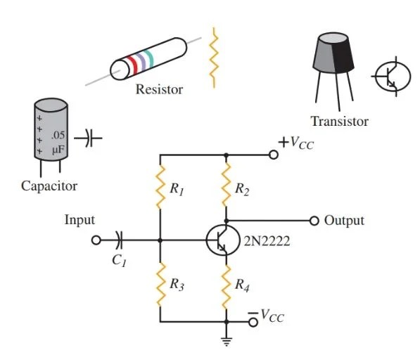
Physics Tutorial Circuit Symbols And Diagrams

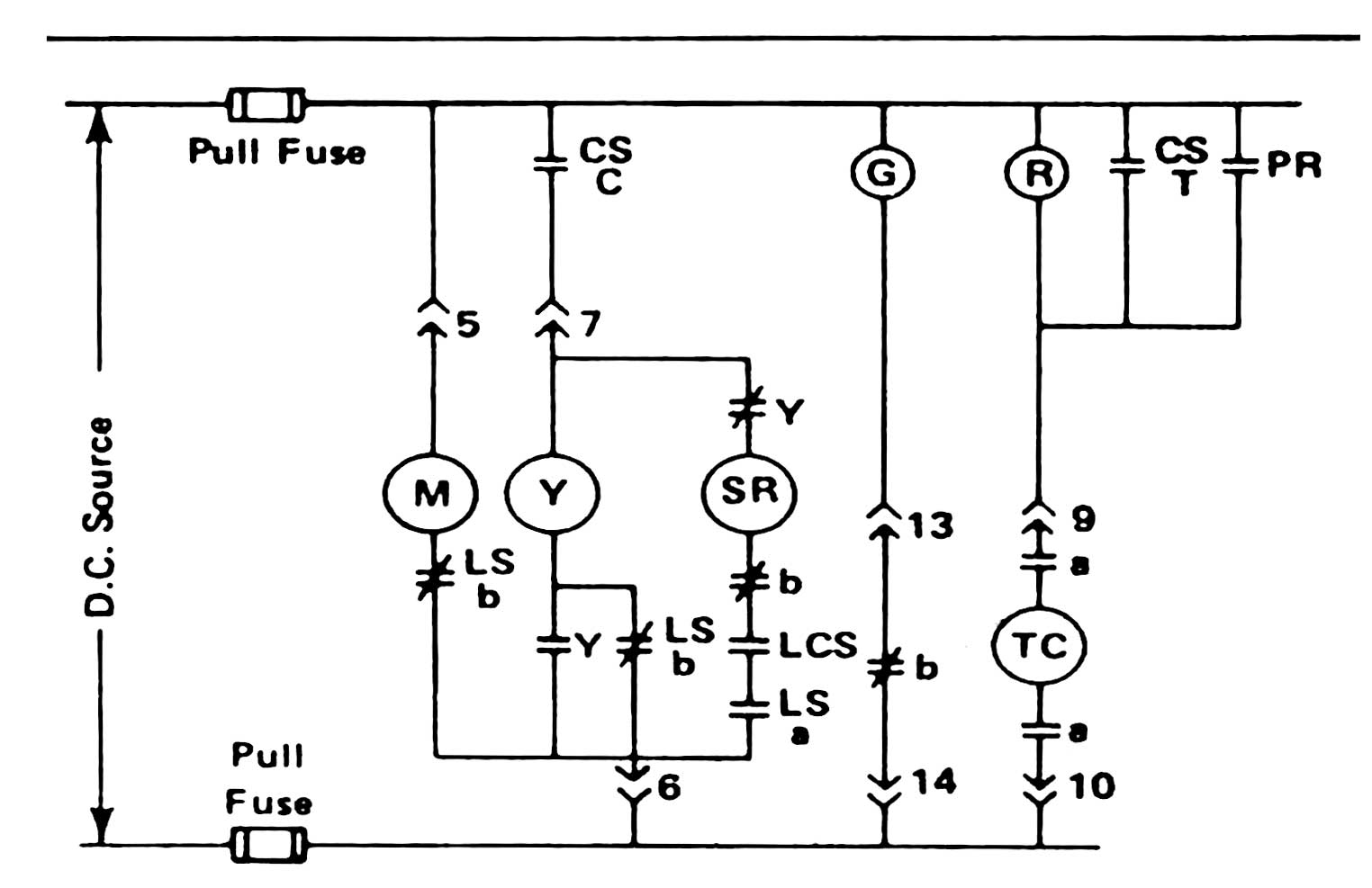
Circuit Breaker Control Schematic Explained

Simplified Schematic Diagram Of The Bms Integrated Circuit Ic Direct Scientific

What Is The Meaning Of Schematic Diagram Sierra Circuits

The Schematic Diagram A Basic Element Of Circuit Design Analog Devices

How To Draw Schematic Diagrams

Re Drawing Complex Schematics Series Parallel Combination Circuits Electronics Textbook

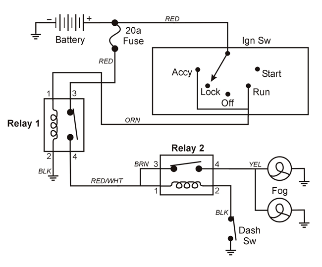
How To Read Automotive Wiring Diagrams Vehicle Service Pros

Electrical Schematic Diagram Elementary Wiring A2z

Schematic Diagram For Sensor Read Out Circuit Scientific

Difference Between Pictorial And Schematic Diagrams Lucidchart Blog

Schematics And Wiring Diagrams Circuit 1

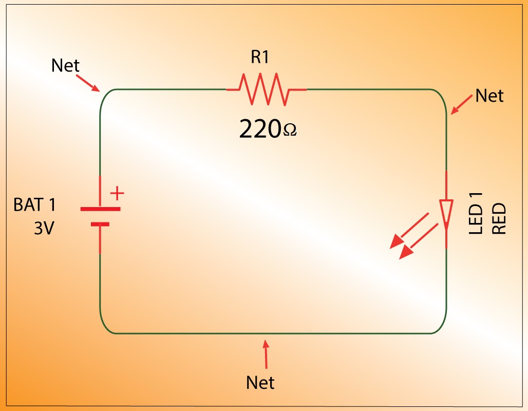
Solved Draw The Schematic Diagram For A Simple Flashlight Chegg Com

Prodemand Wiring Diagrams Mitc 1

Schematic Diagrams Of A Interface Circuit With Biasing Capacitor And Scientific Diagram

Figure 4 1 Schematic Diagram Of The Ventilator And Circuit Oxford Medicine Online

Schematic Diagram Of Circuit Breaker Opening And Closing Nader

L2 Circuit Schematics Physical Computing