Radio-Frequency Identification (RFID) technology has rapidly gained popularity in the past few years, allowing businesses to better manage inventory and secure valuable assets. With RFID, a circuit diagram helps users to easily read and store data on RF tags. It comprises of electrical components such as antennas, RFID modules, and an microcontroller that helps to decode and transmit data.
Building your own RFID circuit diagram is easy and cost effective. Firstly, you need to identify the components and their electrical specifications. Antennas are used to receive and transmit RF signals and it is important to purchase one which is compatible with the RFID module. The RFID module reads and writes data to RFID tags, and then the microcontroller decodes the data. Next, you would need to set up power supply, either using a battery or connecting it to the mains. Once all components are ready, you can assemble the circuit diagram following the datasheet provided with the individual components.
Nowadays, businesses are increasingly leveraging the benefits of RFID circuit diagrams. With a circuit diagram, businesses are able to efficiently manage their inventory using automated processes. The data stored in the RFID tag can now be read quickly and accurately using the circuit diagram. Additionally, RFID circuit diagrams can also be used to remotely monitor and secure assets, ensuring business continuity and efficiency.

Basic Of Rfid System Types And Working Example Application

Circuit Diagram Of Rfid Reader 12 Scientific

Schematic Diagram Of Rfid Reader Scientific

Figure 1 Low Power Clock Recovery Circuit For Passive Hf Rfid Tag Springerlink

Rfid Tag Overcomes Metal Interference Embedded Com

Rfid Access Control System With Two Factor Authentication Via Sms Projectgics

How To Interface Rfid With Arduino Uno Circuit Diagram And Code

Rfid Schematic Resources Easyeda

How Rfid Works Antenna Design Eagle Blog

Arduino Rfid Door Lock Home Automation

Developing A Uhf Rfid Reader Rf Front End With An Analog Devices Solution

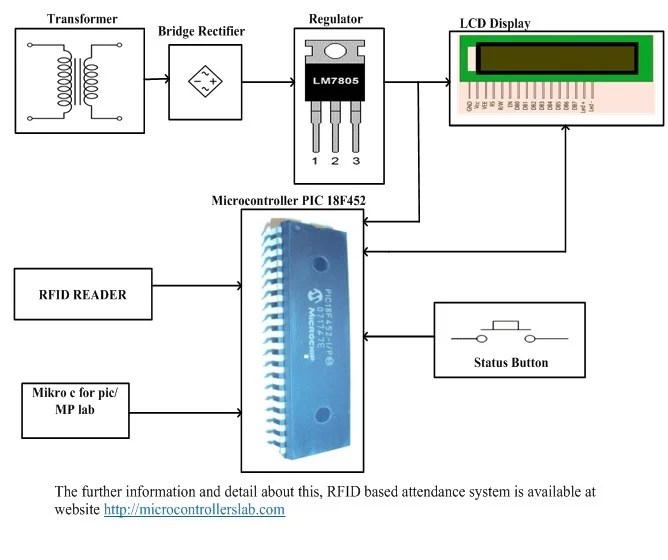
Rfid Based Attendance System Using Pic Microcontroller

Simplified Schematic Diagram Of The Rfid Reader Scientific

How To Build An Rfid Automated Home Control System Smartech

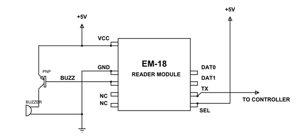
Em18 Rfid阅读器模块pinout Equivalents Circuit Datasheet 乐鱼全站app下载

Interfacing Em 18 Rfid Reader Module With Arduino Uno

Rfid Based Attendance System Using 8051 Microcontroller Project With Circuit Diagram Code

Build Own Rfid Circuit Technology Talk Techtalk

Interface Rc522 Rfid 13 56mhz Reader Writer Module With Arduino Electrovigyan