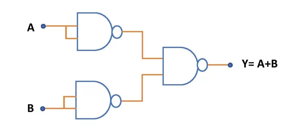
Nand Gate Transistor Diagram is one of the essential components in the world of electronics. It is used in a variety of applications ranging from simple circuit designs to complex computer systems. It is also used extensively in digital logic and signal processing applications. The use of this technology dates back to the 1950s, when transistors first started to become widely available.
The Nand Gate Transistor Diagram consists of two transistors connected together in a gate arrangement. The transistors are usually arranged side-by-side, in a form that looks like two small boxes. Inside each box is a single transistor, and each transistor has its own set of connections that must be properly wired. Each transistor is connected to two other transistors by a single connection. These two transistors are called a “gate”.
The most common application for Nand Gate Transistor Diagrams is digital logic. This means that the diagram is used to represent the logical relationship between two or more digital signals. For example, the diagram can be used to represent the relationship between an input voltage and an output voltage. When two or more signals are applied to the diagram, the relationship between them can be determined. This is especially useful in the design of computers, as it can help to simplify the design process. In addition, the diagram can be used to represent the relationship between the various components of a circuit. By looking at the diagram, it is possible to determine which component is connected to which other component.

Solved Identify The Logic Gate Corresponding To Each Of Chegg Com

Schematic Diagram Of Two Input Transition Nand Gate Tag This Scientific

Transistor Gates

Solved Draw The Circuit Schematic Of A Four Input Nand Gate Supp Chegg Com
Diy Electronics Transistor Nand Gate Electronic Circuits Facebook

Not And Or Gate Using Nand Circuit Diagram Edumir Physics

Logic Gates Hackaday

Npn And Pnp Logic Gates Code Perspectives Stem Intros

Diode And Transistor Nand Gate Or Dtl Ics Electrical4u

A Transistor Circuit Of 3 Input Nand Gate B Excitation For Arc A3 X Scientific Diagram

Explain The Logic Nand Gate With Its Operation And How It Works As A Universal Electronics Post

Basic Cmos Logic Gates Technical Articles

Nand Gate Definition Symbol And Truth Table Of Diagram

Understanding Nand General Electronics Arduino Forum

How To Build A Nand Gate Logic Circuit Using 4011 Chip

Nand Gate Truth Table Circuit Design Applications And Advantages

B Electronics Projects How To Create A Transistor Nand Gate Circuit Dummies

Nand Gate Transistor 15 Images 7410 Triple 3 Input Gates National New Manufacturing Technology Enables Vertical Transistors Bicmos Basics Advantages Disadvantages Devices Physics Hyper Logic
