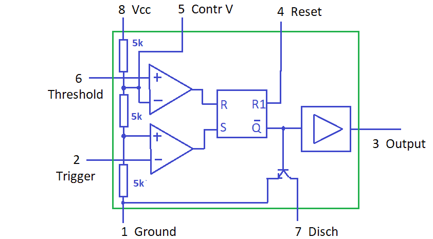
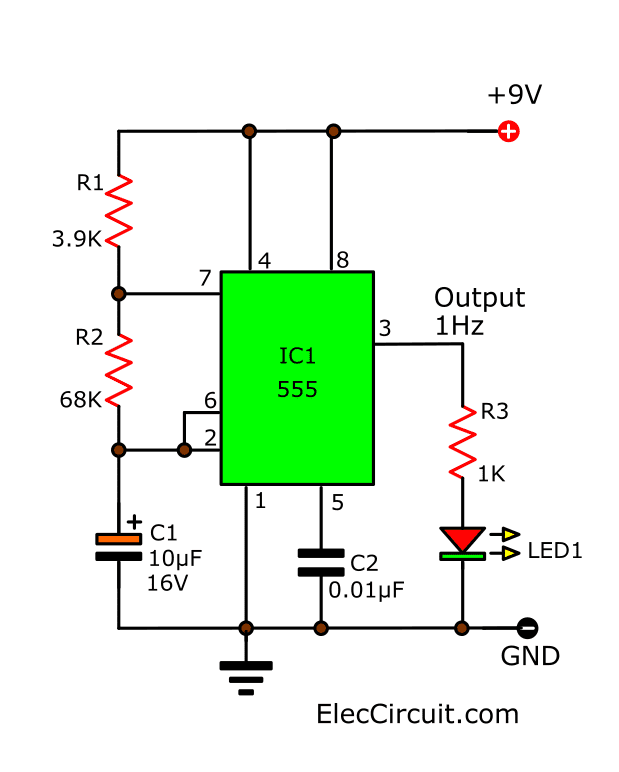
The 555 Pin Diagram, often referred to as the IC 555 or the Timer IC 555, is one of the most widely used integrated circuits in the world. It was first introduced by Texas Instruments in 1971, and has since become a common sight in industrial, automotive, electronic, and computing applications where it is used as an oscillator, timer, signal generator, and voltage regulator. The device can also be used as an analogue computer, counter, pulse generator, and much more.
At its core, the 555 Pin Diagram consists of 8 pins arranged in a dual in-line package (DIP). Each pin has a specific purpose and is responsible for controlling the timing, voltages, and outputs from the device. It is capable of operating at temperatures ranging from -55°C to 125°C, and can generate output frequencies in the range of 0.01Hz to 1MHz, making it suitable for a wide variety of tasks.
The device has been widely used in projects due to its versatility and ease of use. With the help of a few external components, such as resistors and capacitors, the user can easily create customized timers and oscillators. Due to its compact size, it is ideal for applications that require limited space. Its simple design further ensures low cost and easy maintenance. The range of operations offered by this device makes it an extremely versatile choice.

555 Timer Ic Pin Configuration Modes Its Applications

Pin Configuration Of The 555 Timer

Making Of Flashing Blinking Led Circuit Diagram Using 555 Timer Ic

Introduction To The 555 Timer Circuit Basics

Pin Configuration Of The 555 Timer

Boost Converter Circuit Using 555 Timer Ic

555 Timer Ale Circuit Electrical Engineering Electronics Tools

Boost Converter Circuit Using 555 Timer Ic

Circuit Diagram Of Ic555 In Ale Mode The Was As A Scientific

10 Simple Ic 555 Monole Circuits Explored Homemade Circuit Projects

How Does Ne555 Timer Circuit Work Datasheet Pinout Eleccircuit Com

5 20 Minuts Timer Circuit Using Ic 555 Eleccircuit Com

555 Timer Northwestern Mechatronics Wiki

555 Timer Pinout

555 Timer Circuit Basics Working Pin Configuration Block Diagram

555 Timer Ic Pinout Diagrams Features Operating Modes Description Datasheet 乐鱼全站app下载

555 Timer Tutorial Pin Diagram Specifications Features

Cmos Ic Lmc555 Datasheet Works With 1 5 V Supply Homemade Circuit Projects