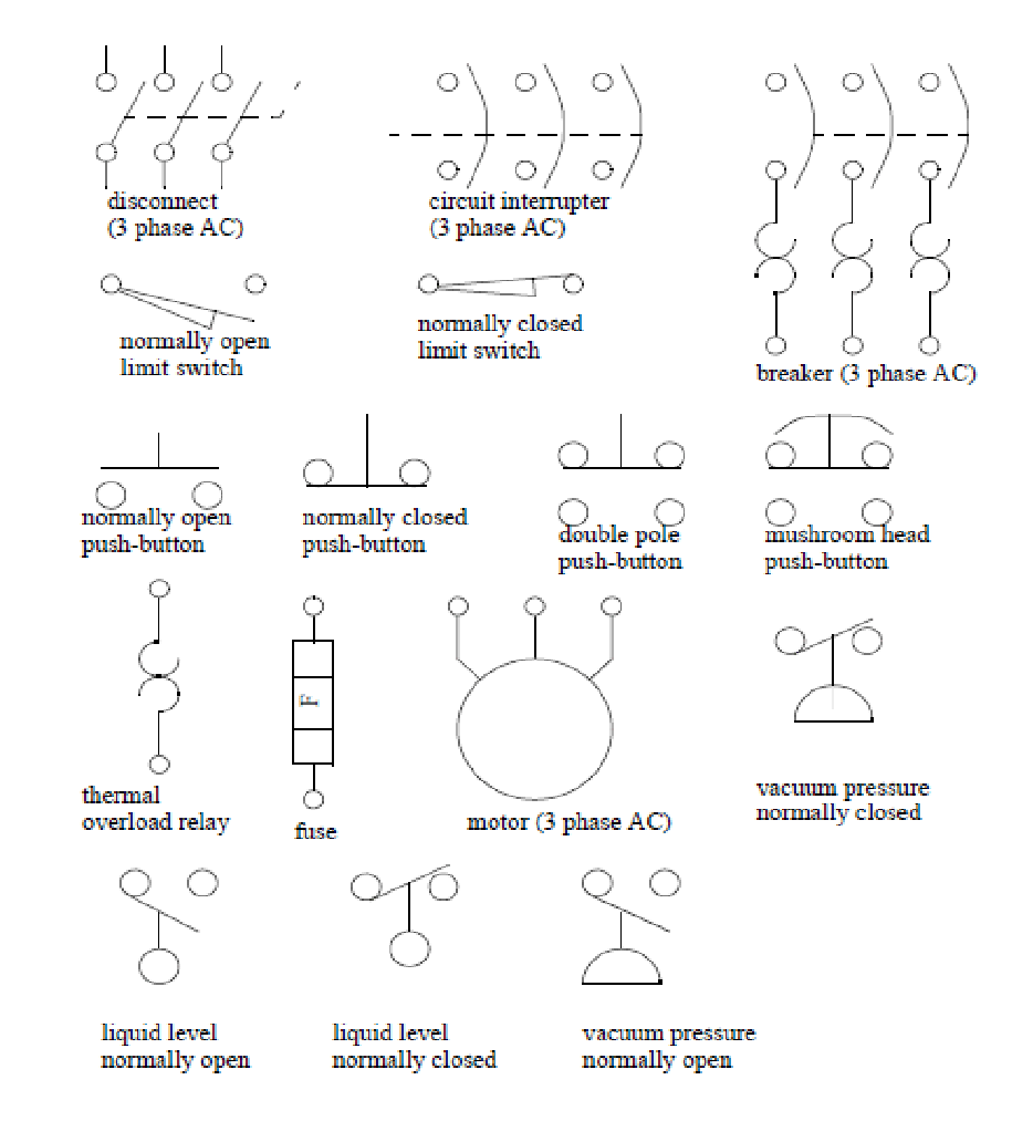
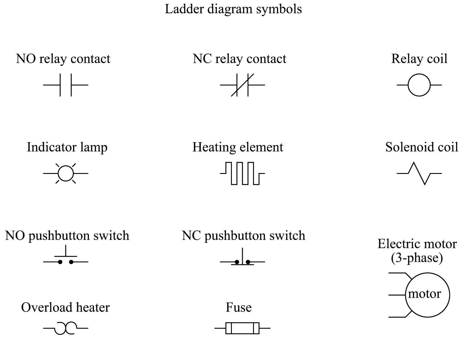
An electric control circuit diagram is a powerful tool used to understand the behavior of an electrical system. By utilizing these symbols, engineers are able to develop and troubleshoot electrical systems more efficiently than ever before. Many of these symbols are standardized throughout the industry, such as for power sources, interconnected components, switches, contactors, and wiring diagrams. However, there are also a number of specialized control circuit symbols that can be used to perform specific tasks, such as setting timers, controlling motors, determining duty cycles, and others.
In order to properly interpret these symbols and diagrams, it is important to be familiar with the basics of control systems. Generally speaking, these systems involve a set of input signals, a set of output signals, and the mechanisms used to control the system. Control systems use feedback loops to receive input from sensors, transducers, or other means, and then use the information to adjust the system until the desired behavior is achieved. Common control systems include open loop control systems, closed loop control systems, and application specific control systems. Depending on the type of the system being controlled, the components of the control circuit may vary.
Understanding and mastering electrical control circuit diagram symbols is essential for any electrical engineer. With these symbols, engineers are able to develop and troubleshoot electrical systems more effectively and efficiently than ever before. By having a thorough knowledge of these symbols, engineers are better equipped to manage and maintain their electrical systems in an efficient manner. As such, it is important to become familiar with electrical control circuit symbols in order to become an effective electrical engineer.

Plc Training Reading Electrical Wiring Diagrams And Understanding Schematic Symbols Tw Controls

Introduction To Relay Logic Control Symbols Working And Examples

Motor Control Symbols And Schematic Diagrams

Electrical Schematic Symbols Input Devices Petroed

Electrical Panel Wiring Diagram

Electrical And Electronics Symboleanings Edrawmax Online

Why Numbering Like 88 51 Are In Electrical Circuit Diagram Meto

Wiring Diagram Everything You Need To Know About

Wiring Design Electrical Circuit Schematics Solid Edge

Appendix C Circuit Schematic Symbols Applied Electricity

How To Read A Schematic Learn Sparkfun Com

Common Electrical Symbols

Electrical Symbols Schematic

Schematic Symbols The Essential You Should Know

Electrical Symbols Analog And Digital Logic

Circuit Schematic Symbols Atmega32 Avr

Jic Standard Symbols For Electrical Ladder Diagrams Womack Machine Supply Company

Electrical Wiring Diagram Switches Symbols Automation Plc Programming Scada Pid Control System

Relay Circuits And Ladder Diagrams Control Systems Automation Textbook