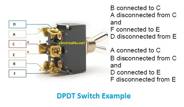
DPDT Circuit Diagrams are widely used in the construction of electronic projects. They provide a convenient way to connect multiple components, allowing for complex combinations that would otherwise be difficult to configure. With the right layout and components, these circuits can be used to create reliable and efficient solutions that power your electronics and provide an extended lifespan.
When creating a DPDT circuit diagram, there are several elements to consider. The first is the overall design – this will typically involve a series of transistors, resistors, capacitors, and connecting wires. It’s important to pay close attention to the layout of the components, as well as their physical relationship to one another. For example, if you’re using a capacitor to buffer signals, it should be placed near the transistor so that it doesn’t interfere with the signal’s path. Additionally, the wires need to be properly color-coded to ensure the electrical current flows correctly.
Once the diagram is created, it’s important to test it out. This can be done with a multimeter or other device that can measure the electrical current. Checking the voltage output should be done before connecting the circuit to any external device. This will help to ensure that the circuit is functioning correctly and that nothing is getting overloaded. After the testing is complete, it’s just a matter of plugging the circuit into the device and using it as it was designed.
DPDT Circuit Diagrams are a great way to quickly create complex electronic devices. They provide an efficient way to solve various issues and configurations, allowing users to enjoy the benefits of their projects. With the right components and careful attention to detail, anyone can create reliable and efficient solutions for powering their electronic devices.

How To Wire A Dpdt Switch As 4 Way For Multiway Switching Tech Tips Engineering And Component Solution Forum Techforum Digi Key

Double Pole Throw Dpdt Switch

A Circuit Block Diagram Of Conventional Spdt Switches B Concept Scientific

How Does A Dpdt Relay Work

Dpdt Double Pole Throw Working Circuit Diagram Application Electrical4u

Flasher Circuit With Dpdt Relay Works For Any Wattage Load Deeptronic
Jaguar Hss Wiring Using Dpdt Switches Guitarnutz 2

Double Pole Throw Dpdt Switch

Dpdt Relay

Spdt Relay Switch Circuit Using Triac Homemade Projects

Schematic Ilrations Of Four Common Switch Functions 1 S1 Scientific Diagram

A Wiring Diagram For Double Pole Throw Dpdt Switch That Scientific

Seymour Duncan Guitar Wiring Explored Dpdt On Switch

On And Switch Basics Learn Sparkfun Com

Dpst Relay
Switches Ultimate Electronics Book