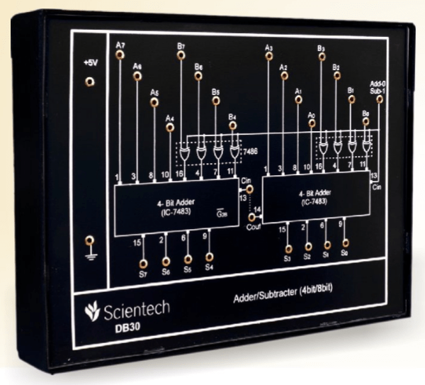
A digital circuit is an important building block of electronic gadgets and devices. With advances in integrated circuit technologies, the complexity of digital circuits has grown exponentially over the years. However, the fundamentals of digital circuits remain the same - Boolean logic, binary counting systems, and arithmetic operations. One of the most commonly used circuits is the 4-bit binary adder, realized using an integrated circuit known as an IC 7483.
The IC 7483 is a 4-bit binary adder integrated circuit, used for addition and overflow detection of two 4-bit binary words. This IC is also known as a 4-bit ripple carry adder, or just 4-bit adder. The 4-bit binary adder using IC 7483 can be used in applications such as digital computers, calculators, and other memory devices.
The circuit diagram for 4-bit binary adder using IC 7483 is straightforward and easily implemented with other basic digital circuits. It consists of four AND gates, each having one input A and one output B. These AND gates are connected in series, so that the output from one gate is sent to the input of the next gate. The output of the last AND gate is sent to the input of the first AND gate, forming a loop. The output of this loop is then sent to the IC 7483, where the 4-bit binary addition is performed. The output of the 7483 is then fed back into the 4-AND gate loop, creating a ripple-carry effect, which is necessary for calculating the output for larger binary words.
The 4-bit binary adder using IC 7483 provides a simple yet effective solution for adding two 4-bit binary words. Its ease of implementation and low cost make it a popular choice for various digital circuits. Moreover, the basic structure of the 4-bit binary adder is similar to adders of higher bit-length, making this circuit a great learning tool for students and hobbyists.

Solved Lab 4 Binary Adder Subtractor And Multiplier Ics Chegg Com

Solved 2 Design An Adder Subtractor Circuit Using 7483 And Chegg Com

Design An Eight Bit Adder Subtractor Circuit Using Four Binary Adders Type Number 7483 And Quad Two Input Ex Or Gates 7486 Assume That Pin Connection Diagrams Of These Ics Are Available To You
Digital Adder Circuits

Ic Adder Chip Under Repository Circuits 45942 Next Gr

Experiment 4

Full Adder Circuit Theory Truth Table Construction

Chapter 11 Laboratory Experiment Ppt Online
How Would You Convert Your 4 Bit Adder To A Subtractor Quora

Digital Logic

Bcd Adder Circuit Truth Table Block Diagram
Logic Design Laboratory Manual
What Will Be The Simplest Design Of One Bit Bcd Adder Quora
Digital Adder Circuits

7483 Technical Data

Adder Subtracter 4 Bit 8 Amplelab

Decimal Or Bcd Adder Javatpoint

Parallel Adder And Subtractor Block Diagram
Experiments No 6 11 Amittal