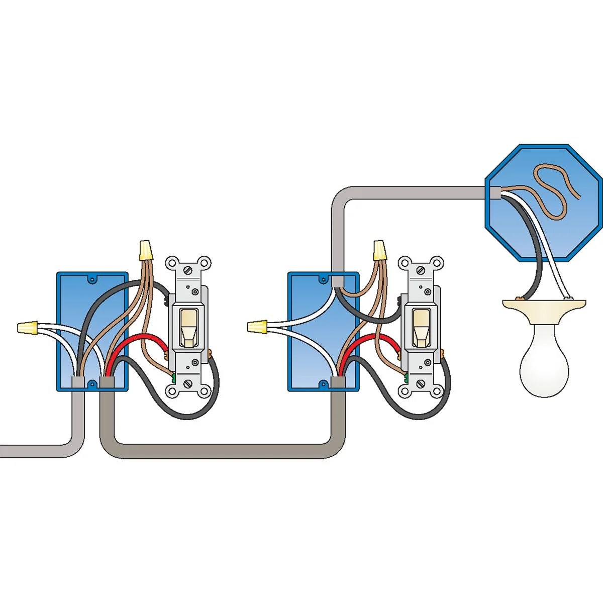
Building wiring installation is an important component of the process of connecting a building to electrical power. It involves laying down cables, connecting them to electrical outlets, and also includes the necessary protection from electric shocks that ensure the safety of the building's occupants. A wiring installation diagram is a visual representation of the various components and connections used in the installation. This type of diagram can be extremely useful in helping to understand how the various components interact with one another in order to create a safe and efficient power supply network.
Creating a wiring installation diagram is a complex and detailed task, but it is essential if you want to be sure that your building is absolutely safe from any potential electrical hazards. The diagram should include every single component of the system, including the cables, outlets, and other components such as switches and circuit breakers. It should also show how they all connect together and indicate the type of wire used. This will help to prevent future problems, as it will allow for easy identification of any faulty wiring.
In addition to safety, a wiring installation diagram also allows for quick repairs and troubleshooting, should something go wrong with the system. By following the diagrams, technicians and engineers can quickly identify and fix any issues with the wiring. This gives them peace of mind knowing that all components are connected properly, allowing them to focus more on ensuring the safety of the building's occupants. With a correctly laid out wiring installation diagram, a building can be powered without any concern of potential hazards.

House Wiring Diagram Everything You Need To Know Edrawmax Online

House Wiring Diagram Everything You Need To Know Edrawmax Online

Free House Wiring Diagram Software Edrawmax Online
Home Electrical Wiring Diagram Apps On Google Play

Electrical Drawings And Schematics Overview

Wiring Diagram Everything You Need To Know About

Electrical Load Diagram Of The Building Scientific

How To Start With The Design Of Electrical Installation Eep

Single Line Diagram How To Represent The Electrical Installation Of A House Stacbond

How To Map House Electrical Circuits

Your Home Electrical System Explained

Installing Communication Wiring Diy Family Handyman

A C Electrical Wiring Information For North America Free Knowledge Base The Duck Project Everyone
Building Electrical Installation Work Photos Facebook

Electrical Installation Testing Procedures Your Guide

How To Wire A 3 Way Light Switch Diy Family Handyman

11 Step Procedure For A Successful Electrical Circuit Design Low Voltage

Electrical Drawing For Architectural Plans
