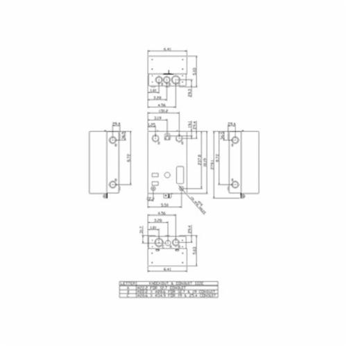
A 120/240 Motor Wiring Diagram is an important tool when it comes to safely and properly wiring an electric motor. This diagram shows the basic circuit connections between a three-phase electrical motor, its associated motor starter, motor overload protector, and motor control circuit breakers. It also outlines important safety information such as proper grounding of equipment and provides guidance on what types of wiring should be used for different types of motors.
When it comes to understanding and using 120/240 Motor Wiring Diagrams, knowledge of electrical terms and components is essential. To start, it is important to understand that there are two basic components of any electric motor - the stator and the rotor. The stator consists of two stationary parts which are connected together with a rotating coil that produces an alternating current. The rotor is a series of windings that form the magnetic field in response to the stator's current. It is important to know how these two components interact with each other and how each contributes to the proper functioning of the motor.
Using a 120/240 Motor Wiring Diagram is fairly easy. The diagram will show the stator and rotor connections so that they can be properly wired together. It will also outline the appropriate wiring and connections needed to connect the motor to its associated control circuit breakers and motor overload protectors. Furthermore, it will provide safety information regarding the grounding of equipment and what types of wiring should be used. By following this wiring diagram, one can ensure a safe and trouble-free electric motor installation.

Asi Motor Reversing Switch Single Phase Momentary 2 Pole 1 5 Hp At 120 Vac 2hp 240 Volt Ac P0202500s Ekit

Ee25s3h Low Voltage Transformer Doe 2016 Dry Type 1 Phase 25kva 240x480v Pri 120 240v Sec Al 150c Rise 2 Schneider Electric Usa

Use A Single Inverter To Run Two 120v Breaker Bus For 240 Volt Setup Forest River Forums

Granite Electrical Troubleshooting Detroit Machine Tools

Sawmill Creek Woodworking Community

Electric Motor Diagrams

Motor Circuits And Control Applied Electricity

Electric Motor Diagrams

Four Wire Delta Circuits Continental Control Systems Llc
Electrical Tech Note 103

Small Sel Generators Wiring Diagrams

Show Tell Ac Induction Motors

Electricity 101 Basic Fundamentals Controls
Siemens 14cuc32ba Class 14 Full Voltage Non Reversing Motor Starter 110 To 120 220 240 Vac Coil 3 Poles Steiner Electric Company

Electric Motor Diagrams

Capacitor Start Motors Diagram Explanation Of How A Is To Single Phase Motor Bright Hub Engineering

Emerson Electric Motor Wiring Help Doityourself Com Community Forums

How Do You Wire A Hps Single Phase Transformer With 240v 120v Secondary To An Electrical Panelboard

Single Phase Motor 208v Electrician Talk
